CHAPTER 16 I
2
C BUS
User’s Manual U16896EJ2V0UD
523
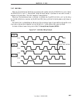
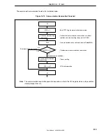
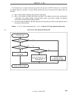
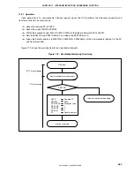
The following shows an example of the processing of the slave device by an INTIIC0 interrupt (it is assumed that
no extension codes are used here). During an INTIIC0 interrupt, the status is confirmed and the following steps are
executed.
<1> When a stop condition is detected, communication is terminated.
<2> When a start condition is detected, the address is confirmed. If the address does not match, communication
is terminated. If the address matches, the communication mode is set and wait is released, and operation
returns from the interrupt (the ready flag is cleared).
<3> For data transmission/reception, when the ready flag is set, operation returns from the interrupt while the I
2
C0
bus remains in the wait status.
Remark
<1> to <3> in the above correspond to <1> to <3> in
Figure 16-19 Slave Operation Flowchart (2)
.
Figure 16-19. Slave Operation Flowchart (2)
Yes
Yes
Yes
No
No
No
INTIIC0 occurred
Set ready flag
Interrupt servicing completed
SPD0 = 1?
STD0 = 1?
COI0 = 1?
Clear communication
direction flag, ready flag,
and communication mode flag
<1>
<2>
<3>
Communication direction flag
←
TRC0
Set communication mode flag
Clear ready flag
<R>

