


CHAPTER 8 8-BIT TIMER/EVENT COUNTER 5
User’s Manual U16896EJ2V0UD
294
8.2 Configuration
8-bit timer/event counter 5n consists of the following hardware.
Table 8-1. Configuration of 8-Bit Timer/Event Counter 5n
Item Configuration
Timer registers
8-bit timer counters 50, 51 (TM50, TM51)
16-bit timer counter 5 (TM5): Only when using cascade connection
Registers
8-bit timer compare registers 50, 51 (CR50, CR51)
16-bit timer compare register 5 (CR5): Only when using cascade connection
Timer output
TO50, TO51
Control registers
Note
Timer clock selection registers 50, 51 (TCL50, TCL51)
8-bit timer mode control registers 50, 51 (TMC50, TMC51)
16-bit timer mode control register 5 (TMC5): Only when using cascade connection
Note
When using the functions of the TI5n and TO5n pins, refer to
Table 4-12 Settings When Port Pins Are Used
for Alternate Functions
.
Remark
n = 0, 1
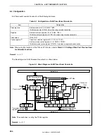
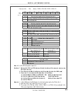
The block diagram of 8-bit timer/event counter 5n is shown below.
Figure 8-1. Block Diagram of 8-Bit Timer/Event Counter 5n
OVF
TI5n
3
TCL5n2 TCL5n1 TCL5n0
TCE5n TMC5n6 TMC5n4 LVS5n LVR5n TMC5n1 TOE5n
TO5n
INTTM5n
S
R
Q
INV
S
R
Q
Match
Clear
Count clock
Note
Selector
Internal bus
Internal bus
8-bit timer mode control
register 5n (TMC5n)
8-bit timer compare
register 5n (CR5n)
8-bit timer
counter 5n
(TM5n)
Selector
Invert
level
Mask circuit
Timer clock selection
register 5n (TCL5n)
Selector
Selector
CSI0 serial
clock
Note
The count clock is set by the TCL5n register.
Remark
n = 0, 1


