CHAPTER 6 16-BIT TIMER/EVENT COUNTER P (TMP)
User’s Manual U16896EJ2V0UD
212
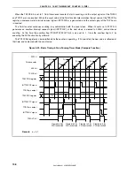
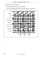
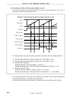
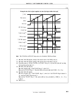
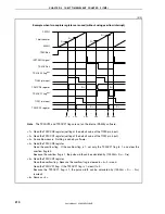
Example when capture trigger interval is long
FFFFH
16-bit counter
0000H
TP0CE bit
TIP0a pin input
TP0CCRa register
INTTP0OV signal
TP0OVF bit
Overflow
counter
Note
D
a0
D
a1
1H
0H
2H
0H
D
a0
D
a1
<1> <2>
<3> <4>
1 cycle of 16-bit counter
Pulse width
Note
The overflow counter is set arbitrarily by software on the internal RAM.
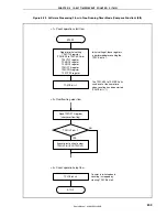
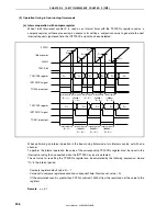
<1> Read the TP0CCRa register (setting of the default value of the TIP0a pin input).
<2> An overflow occurs. Increment the overflow counter and clear the overflow flag to 0 in the overflow
interrupt servicing.
<3> An overflow occurs a second time. Increment (+1) the overflow counter and clear the overflow flag
to 0 in the overflow interrupt servicing.
<4> Read the TP0CCRa register.
Read the overflow counter.
→
When the overflow counter is “N”, the pulse width can be calculated by (N
×
D
a1
–
D
a0
).
In this example, the pulse width is ( D
a1
– D
a0
) because an overflow occurs twice.
Clear the overflow counter (0H).

