CHAPTER 9 8-BIT TIMER H
User’s Manual U16896EJ2V0UD
335
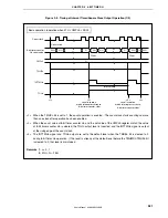
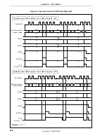
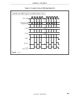
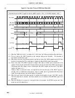
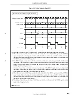
Figure 9-8. Carrier Generator Mode (3/3)
Operation based on CMPn1 register transitions
8-bit timer Hn count clock
CMPn0
TMHEn
INTTMHn
Carrier clock
00H 01H
N
00H 01H
01H
M
00H
N
00H
L
00H
<1>
<3>’
<4>
<3>
<2>
CMPn1
<5>
M
N
L
M (L)
8-bit timer counter
Hn count value
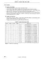
<1> When the TMHEn bit is set to 1, counting starts. The carrier clock remains the default level at this time.
<2> When the count value of the 8-bit timer counter Hn matches the value of the CMPn0 register, the INTTMHn
signal is output, the carrier signal is inverted, and the 8-bit timer counter is cleared to 00H. At the same time,
the compare register whose value is to be compared with that of the 8-bit timer counter Hn is changed from
the CMPn0 register to the CMPn1 register.
<3> The CMPn1 register is asynchronous to the count clock, and its value can be changed while the 8-bit timer Hn
is operating. The new value (L) to which the value of the register is to be changed is latched. When the count
value of the 8-bit timer counter Hn matches the value (M) of the CMPn1 register before the change, the
CMPn1 register is changed (<3>’).
However, it takes three count clocks or more since the value of the CMPn1 register has been changed until
the value is transferred to the register. Even if a match signal is generated before the duration of three count
clocks elapses, the new value is not transferred to the register.
<4> When the count value of 8-bit timer counter Hn and the value (M) of the CMPn1 register match, the INTTMHn
signal is output, the carrier signal is inverted, and 8-bit timer counter Hn is cleared to 00H. At the same time,
the compare register whose value is to be compared with that of the 8-bit timer counter Hn is changed from
the CMPn1 register to the CMPn0 register.
<5> The timing at which the count value of 8-bit timer counter Hn and the value of the CMPn1 register match
again is the changed value (L).
Remark
n = 0, 1
<R>
<R>
<R>
<R>

