CHAPTER 7 16-BIT TIMER/EVENT COUNTER 0
User’s Manual U16896EJ2V0UD
263
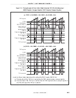
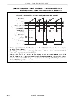
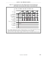
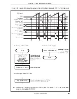
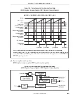
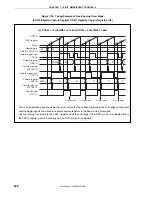
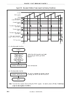
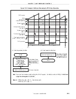
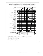
Figure 7-24. Timing Example of Free-Running Timer Mode
(CR010 Register: Compare Register, CR011 Register: Compare Register)
•
TOC01 = 13H, PRM01 = 00H, CRC01 = 00H, TMC01 = 04H
FFFFH
TM01 register
0000H
Operable bits
(TMC013, TMC012)
Compare register
(CR010)
Compare match interrupt
(INTTM010)
Compare register
(CR011)
Compare match interrupt
(INTTM011)
TO01 pin output
Overflow flag
(OVF01)
01
M
N
M
N
M
N
M
N
00
00
N
0 write clear
0 write clear
0 write clear
0 write clear
M
This is an application example where two compare registers are used in the free-running timer mode.
The output level of the TO01 pin is reversed each time the count value of the TM01 register matches the set
values of the CR010 and CR011 registers. When the count value matches the register value, the INTTM010 or
INTTM011 signal is generated.
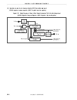
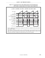
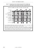
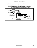
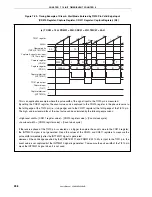
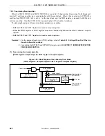
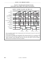
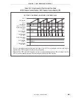
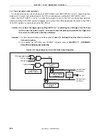
(2) Free-running timer mode operation
(CR010 register: compare register, CR011 register: capture register)
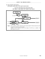
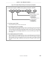
Figure 7-25. Block Diagram of Free-Running Timer Mode
(CR010 Register: Compare Register, CR011 Register: Capture Register)
16-bit counter
(TM01)
Output
controller
Edge
detection
Capture register
(CR011)
Capture signal
TO01 pin
Match signal
Interrupt signal
(INTTM010)
Interrupt signal
(INTTM011)
TI010 pin
Compare register
(CR010)
Operable bits
TMC013, TMC012
Count clock

