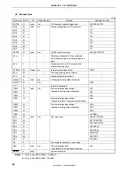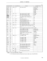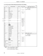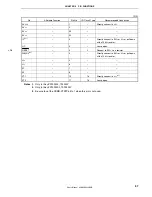
CHAPTER 1 INTRODUCTION
User’s Manual U16896EJ2V0UD
25
1.5 Pin Configuration (Top View)
64-pin plastic TQFP (12
×
12)
64-pin plastic LQFP (fine pitch) (10
×
10)
μ
PD703302GK-
×××
-9ET-A
μ
PD703302GB-
×××
-8EU-A
μ
PD703302YGK-
×××
-9ET-A
μ
PD703302YGB-
×××
-8EU-A
μ
PD70F3302GK-9ET-A
μ
PD70F3302GB-8EU-A
μ
PD70F3302YGK-9ET-A
μ
PD70F3302YGB-8EU-A
1
2
3
4
5
6
7
8
9
10
11
12
13
14
15
16
48
47
46
45
44
43
42
41
40
39
38
37
36
35
34
33
P70/ANI0
P71/ANI1
P72/ANI2
P73/ANI3
P74/ANI4
P75/ANI5
P76/ANI6
P77/ANI7
P39/SCL0
Note 3
P38/SDA0
Note 3
PDL7
PDL6
PDL5/FLMD1
Note 1
PDL4
PDL3
PDL2
P05/INTP2
P06/INTP3
P40/SI00
P41/SO00
P42/SCK00
P30/TXD0
P31/RXD0/INTP7
P32/ASCK0/ADTRG/TO01
P33/TIP00/TOP00
P34/TIP01/TOP01
P35/TI010/TO01
P50/KR0/TI011/RTP00
P51/KR1/TI50/RTP01
P52/KR2/TO50/RTP02
P53/KR3/RTP03
EV
SS
PDL1
PDL0
PCM1/CLKOUT
PCM0
P915/INTP6
P914/INTP5
P913/INTP4
P99/SCK01
P98/SO01
P97/SI01
P96/TI51/TO51
P91/KR7/RXD1
P90/KR6/TXD1
P55/KR5/RTP05
P54/KR4/RTP04
EV
DD
AV
REF0
AV
SS
IC
Note 1
/FLMD0
Note 1
V
DD
NC
Note 2
V
SS
X1
X2
RESET
XT1
XT2
P00/TOH0
P01/TOH1
P02/NMI
P03/INTP0
P04/INTP1
64 63 62 61 60 59 58 57 56 55 54 53 52 51 50 49
17 18 19 20 21 22 23 24 25 26 27 28 29 30 31 32
Notes 1.
IC pin:
Connect directly to V
SS
(
μ
PD703302, 703302Y).
FLMD0 pin: Connect to V
SS
in normal operation mode (
μ
PD70F3302, 70F3302Y).
FLMD1 pin: Used only in the
μ
PD70F3302 and 70F3302Y.
2.
Leave the NC pin open.
3.
The SCL0 and SDA0 pins can be used only in the
μ
PD703302Y and 70F3302Y.
Caution Make
EV
DD
the same potential as V
DD
.

