


CHAPTER 7 16-BIT TIMER/EVENT COUNTER 0
User’s Manual U16896EJ2V0UD
230
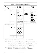
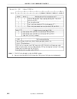
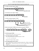
Table 7-2. Capture Operation of CR010 and CR011 Registers
External Input
Signal
Capture
Operation
TI010 Pin Input
TI011 Pin Input
Set values of ES101 and
ES100
Position of edge to be
captured
Set values of ES111 and
ES110
Position of edge to be
captured
01: Rising
01: Rising
00: Falling
00: Falling
CRC011 bit = 1
TI010 pin input
(reverse phase)
11: Both edges
(cannot be captured)
CRC011 bit = 0
TI011 pin input
11: Both edges
Capture operation of
CR010 register
Interrupt signal
INTTM010 signal is not
generated even if value
is captured.
Interrupt signal
INTTM010 signal is
generated each time
value is captured.
Set values of ES101 and
ES100
Position of edge to be
captured
01: Rising
00: Falling
TI010 pin input
Note
11: Both edges
Capture operation of
CR011 register
Interrupt signal
INTTM011 signal is
generated each time
value is captured.
Note
The capture operation of the CR011 register is not affected by the setting of the CRC011 bit.
Caution To capture the count value of the TM01 register to the CR010 register by using the phase
reverse to that input to the TI010 pin, the interrupt request signal (INTTM010) is not generated
after the value has been captured. If the valid edge is detected on the TI011 pin during this
operation, the capture operation is not performed but the INTTM010 signal is generated as an
external interrupt signal. To not use the external interrupt, mask the INTTM010 signal.
Remark
CRC011: Refer to
7.3 (2) Capture/compare control register 01 (CRC01)
.
ES111, ES110, ES101, ES100: Refer to
7.3 (4) Prescaler mode register 01 (PRM01)
.


