CHAPTER 2 PIN FUNCTIONS
User’s Manual U16896EJ2V0UD
34
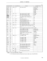
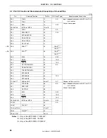
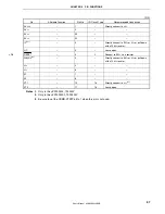
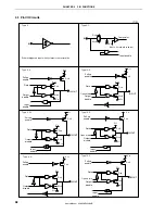
(2) Non-port
pins
(1/2)
Pin Name Pin No.
I/O
Pull-up Resistor
Function Alternate
Function
ADTRG
24
Input
Yes
A/D converter external trigger input
P32/ASCK0/TO01
ANI0 64
P70
ANI1 63
P71
ANI2 62
P72
ANI3 61
P73
ANI4 60
P74
ANI5 59
P75
ANI6 58
P76
ANI7 57
Input
No
Analog voltage input for A/D converter
P77
ASCK0 24 Input Yes
UART0
serial clock input
P32/ADTRG/TO01
AV
REF0
1
–
–
Reference voltage for A/D converter and
positive power supply for alternate-function
ports
–
AV
SS
2
–
–
Ground potential for A/D converter and
alternate-function ports
–
CLKOUT
46
Output
No
Internal system clock output
PCM1
EV
DD
33
–
–
Positive power supply for external
–
EV
SS
32
–
–
Ground potential for external
–
FLMD0
Note 1
3
No
–
FLMD1
Note 1
52
Input
Yes
Flash programming mode setting pin
PDL5
IC
Note 2
3
–
–
Internally
connected
–
INTP0 15
P03
INTP1 16
P04
INTP2 17
External interrupt request input
(maskable, analog noise elimination)
P05
INTP3
18
External interrupt request input
(maskable, d analog noise elimination)
P06
INTP4 42
P913
INTP5 43
P914
INTP6 44
P915
INTP7 23
Input Yes
External interrupt request input
(maskable, analog noise elimination)
P31/RXD0
KR0 28
P50/TI011/RTP00
KR1 29
P51/TI50/RTP01
KR2 30
P52/TO50/RTP02
KR3 31
P53/RTP03
KR4 34
P54/RTP04
KR5 35
P55/RTP05
KR6 36
P90/TXD1
KR7 37
Input
Yes
Key return input
P91/RXD1
NC
5
–
–
Not internally connected. Leave open.
–
NMI
14
Input
Yes
External interrupt input
(non-maskable, analog noise elimination)
P02
RESET
9
Input
–
System reset input
–
Notes 1.
Only in the
μ
PD70F3302, 70F3302Y
2.
Only in the
μ
PD703302, 703302Y


