CHAPTER 8 8-BIT TIMER/EVENT COUNTER 5
User’s Manual U16896EJ2V0UD
311
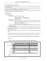
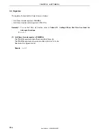
8.4.7 Square-wave output operation (16-bit resolution)
The 16-bit resolution timer/event counter mode is selected by setting the TMC51.TMC514 bit to 1.
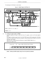
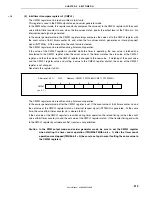
8-bit timer/event counter 5n outputs a square wave of any frequency using the interval preset in 16-bit timer
compare register 5 (CR5).
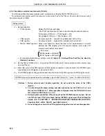
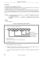
Setting method
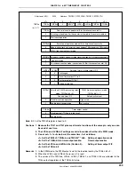
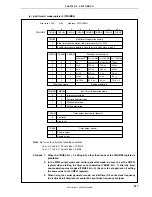
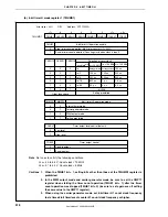
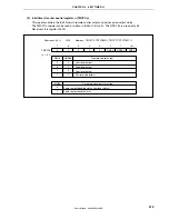
<1> Set each register.
•
TCL50 register:
Selects the count clock (t)
(The TCL51 register does not have to be set in cascade connection)
•
CR50 register:
Compare value (N) ... Lower 8 bits (settable from 00H to FFH)
•
CR51 register:
Compare value (N) ... Higher 8 bits (settable from 00H to FFH)
•
TMC50, TMC51 registers: Stops count operation, selects the mode in which clear & start occurs on a
match between the TM5 register and CR5 register.
LVS50
LVR50
Timer Output F/F Status Settings
1 0
High-level
output
0 1
Low-level
output
Enables timer output F/F inversion, and enables timer output.
TMC50 register = 00001011B or 00000111B
TMC51 register = 00010000B
•
For the alternate-function pin settings, refer to
Table 4-12 Settings When Port Pins Are Used for
Alternate Functions.
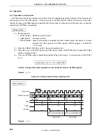
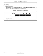
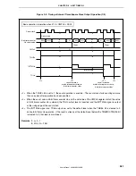
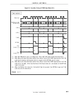
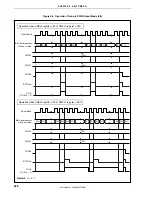
<2> Set the TMC51.TCE51 bit to 1. Then set the TMC50.TCE50 bit to 1 to start the count operation.
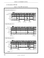
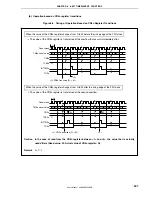
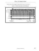
<3> When the values of the TM5 register and the CR5 register connected in cascade match, the TO50 timer
output F/F is inverted. Moreover, the INTTM50 signal is generated and the TM5 register is cleared to
0000H.
<4> Then, the timer output F/F is inverted during the same interval and a square wave is output from the TO50
pin.
Frequency = 1/2t(N + 1): N = 0000H to FFFFH
Caution Do not write a different value to the CR5 register during operation.

