CHAPTER 26 FLASH MEMORY
User’s Manual U16896EJ2V0UD
627
26.2 Memory Configuration
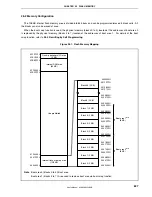
The 128 KB internal flash memory area is divided into 64 blocks and can be programmed/erased in block units. All
the blocks can also be erased at once.
When the boot swap function is used, the physical memory (blocks 0 to 3) located at the addresses of boot area 0
is replaced by the physical memory (blocks 4 to 7) located at the addresses of boot area 1. For details of the boot
swap function, refer to
26.5 Rewriting by Self Programming
.
Figure 26-1. Flash Memory Mapping
Block 0 (2 KB)
Block 1 (2 KB)
Block 2 (2 KB)
Block 3 (2 KB)
Block 5 (2 KB)
Block 6 (2 KB)
Block 7 (2 KB)
Block 8 (2 KB)
Block 4 (2 KB)
Block 63 (2 KB)
00007FFH
0000800H
0000FFFH
0001000H
00027FFH
0002800H
0002FFFH
0003000H
00037FFH
0003800H
0003FFFH
0004000H
00047FFH
0004800H
001FFFFH
0020000H
001F7FFH
001F800H
00017FFH
0001800H
0001FFFH
0002000H
0000000H
3FFFFFFH
3FF0000H
3FEFFFFH
3FEC000H
3FEBFFFH
0120000H
0001FFFH
0000000H
Use prohibited
Internal flash memory area
(128 KB)
Boot area 0
Note
(8 KB)
Internal RAM area
(60 KB)
On-chip peripheral I/O area
(4 KB)
Boot area 1
Note
(8 KB)
Note
Boot area 0 (blocks 0 to 3): Boot area
Boot area 1 (blocks 4 to 7): Area used to replace boot area via boot swap function

