background image

Document Revision 4C

Electra Elite IPK II

2 - 1078

Voice Over Internet Protocol (VoIP)


To connect a telephone to a LAN connection, the system allows using an Electra Elite IPK II digital IP 
16-button multiline terminal (called an Electra Elite IPK II IP Phone), an Electra Elite IPK II digital 
multiline terminal with an IP Adapter installed.

If connecting a LAN to a WAN (wide area network), follow the instructions included with the ADSL 
modem or gateway device.

IP Address

Equipment/devices used in the Electra Elite IPK II LAN setup must have an IP address assignment. An 
IP address assigns a unique address for each device. There are two types of IP addresses: Private and 
Global. A Private IP address is not accessible through the internet – a Global IP address can be 
accessed through the internet.

With a Private IP address, with equipment that does not access the internet directly, addresses can be 
assigned to the equipment in Class A, B or C by assigning a number in the class range of numbers.

Class

Allowed IP Address

Recommended 

Environment

A

  10.0.0.0 --- 10.22.255.255

Large Scale Network

B

172.16.0.0 --- 172.31.255.255

Mid Scale Network

C

192.168.0.0 --- 192.168.255.255

Small Scale Network

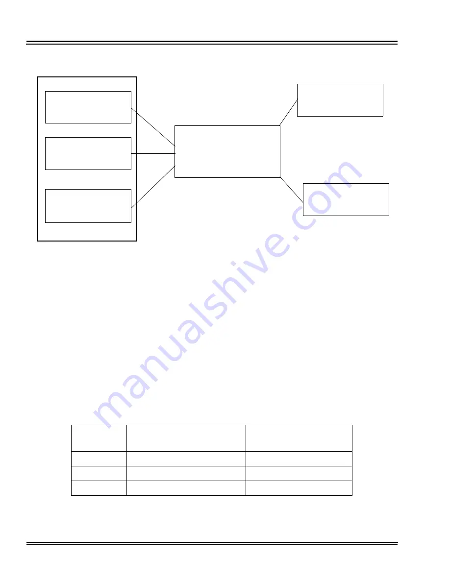
IPK II CPU

Switch

10Base - T/100 Base-T

(100Base-TX is 

recommended)

PVA or IAD

HUB Card

(Switching Hub)

IPK II CPU

IPK II CPU

Summary of Contents for ELECTRA ELITE IPK II

Page 1: ...ormat changes may occur When viewing and printing this document we cannot guarantee that your specific PC or printer will support all of the fonts or graphics Therefore when you view the document fonts may be substituted and your individual printer may not have the capability to print the document correctly ...

Page 2: ......

Page 3: ...FEATURES AND SPECIFICATIONS MANUAL INT 1072 IPK II DOCUMENT REVISION 4C VERSION 2100 ...

Page 4: ......

Page 5: ... Inc Dterm is a registered trademark of NEC Corporation and Electra Elite is a registered trademark of NEC America Inc Windows is a registered trademark of Microsoft Corporation AT T is a registered trademark of American Telephone and Telegraph Company Lucent Technologies is a trademark or service mark of Lucent Technologies Inc Nortel Networks and the Nortel Networks logo are trademarks of Nortel...

Page 6: ......

Page 7: ...bution The Electra Elite IPK II system meets the customer needs today and as business expands the system can be expanded to grow as well The Electra Elite IPK II system has a set of manuals that provide all the information necessary to install and support the system This preface describes these manuals SUPPORTING DOCUMENTS Electra Elite IPK II General Description Manual This Manual provides genera...

Page 8: ...Electra Elite IPK II Programming Manual This manual provides instructions for programming the Electra Elite IPK II system using a Multiline Terminal or PC ...

Page 9: ... 1 Chapter 2 Features Section 1 About This Chapter 2 1 Section 2 Important Notes 2 2 Section 3 IPK to IPK II Feature Comparison List 2 3 Section 4 Features 2 12 Account Code Entry 2 13 Account Code Forced Verified Unverified 2 19 Alarm 2 27 Alarm Reports 2 31 Alphanumeric Display 2 43 Analog Communications Interface ACI 2 45 Ancillary Device Connection 2 53 Answer Hold 2 57 Answer Key 2 59 Attenda...

Page 10: ...127 Call Forwarding Do Not Disturb Override 2 131 Call Forwarding Off Premise 2 133 Call Forwarding Park and Page 2 145 Call Forwarding with Follow Me 2 149 Call Monitoring 2 153 Call Redirect 2 159 Call Waiting Camp On 2 161 Callback 2 165 Caller ID 2 169 Caller ID Call Return 2 183 Central Office Calls Answering 2 187 Central Office Calls Placing 2 195 Class of Service 2 203 Clock Calendar Displ...

Page 11: ...on Tone 2 291 Dial Tone Detection 2 293 Digital Trunk Clocking 2 297 Digital Voice Mail 2 305 Direct Inward Dialing DID 2 321 Direct Inward Line DIL 2 337 Direct Inward System Access DISA 2 341 Direct Station Selection DSS Console 2 353 Directed Call Pickup 2 361 Directory Dialing 2 365 Distinctive Ringing Tones and Flash Patterns 2 369 Do Not Disturb 2 375 Door Box 2 379 Drop Key 2 385 Dterm Cord...

Page 12: ... Call Pickup 2 469 Group Listen 2 473 Handset Mute 2 475 Handsfree and Monitor 2 481 Handsfree Answerback Forced Intercom Ringing 2 485 Headset Operation 2 489 Hold 2 493 Hotel Motel 2 499 Hot Key Pad 2 505 Hotline 2 509 Howler Tone Service 2 513 Intercom 2 515 Internal Hub 2 521 IP Extenders Mobile ConneX 2 527 IP Station MEGACO IAD Integrated Access Device 2 531 IP Station MEGACO MG 16 2 537 IP ...

Page 13: ... 669 Last Number Redial 2 675 Licensing 2 679 Line Preference 2 683 Long Conversation Cutoff 2 687 Meet Me Conference 2 691 Meet Me Paging 2 695 Meet Me Paging Transfer 2 699 Memo Dial 2 703 Message Waiting 2 707 Microphone Cutoff 2 713 Multiline Conference Bridge 2 715 Multimedia Conference Bridge 2 719 Multiple Trunk Types 2 725 Music on Hold 2 735 Name Storing 2 741 Night Service 2 745 Off Hook...

Page 14: ...Pulse to Tone Conversion 2 823 Quick Transfer to Voice Mail 2 825 Redial Key 2 829 Remote System Upgrade 2 831 Repeat Redial 2 835 Resident System Program 2 839 Reverse Voice Over 2 841 Ring Groups 2 845 Ringdown Extension Internal External 2 849 Room Monitor 2 853 Save Number Dialed 2 859 Secondary Incoming Extension 2 863 Secretary Call Buzzer 2 867 Secretary Call Pickup 2 871 Selectable Display...

Page 15: ... Compatibility 2 941 Tandem Ringing 2 949 Tandem Trunking Unsupervised Conference 2 953 TAPI Compatibility 2 967 Tone Override 2 971 Traffic Reports 2 975 Transfer 2 979 Trunk Group Routing 2 991 Trunk Groups 2 995 Trunk Queuing Camp On 2 999 Unified Messaging 2 1003 Uniform Call Distribution UCD 2 1017 Uniform Numbering Network 2 1025 Universal Slots 2 1031 User Programming Ability 2 1049 Virtual...

Page 16: ...________________________________ Document Revision 4C Electra Elite IPK II Wireless DECT 2 1115 Chapter 3 Codes Tables Section 1 About This Chapter 3 1 Section 2 Simplifying Multiline Terminal Operations with One Touch Key Operation 3 1 Section 3 Using Handsfree 3 2 Chapter 4 Feature Availability by Software Revision Section 1 Feature Availability Chart 4 1 ...

Page 17: ... 209 Table 2 9 Class of Service Options Answer Service Program 20 10 2 210 Table 2 10 Class of Service Options Hold Transfer Service Program 20 11 2 211 Table 2 11 Class of Service Options Charging Cost Service Program 20 12 2 214 Table 2 12 Class of Service Options Supplementary Service Program 20 13 2 215 Table 2 13 Class of Service Options for DISA E M Service Program 20 14 2 219 Figure 2 1 Dep...

Page 18: ...ode Setup for Service Access Program 11 12 2 455 Table 2 23 Service Code Setup for ACD Program 11 13 2 457 Table 2 24 Service Code Setup for Hotel Program 11 14 2 458 Table 2 25 Service Code Setup Administrative for Special Access Program 11 15 2 459 Table 2 26 Service Tone Setup Program 80 01 01 2 476 Table 2 27 Service Tone Setup Program 80 01 02 2 480 Figure 2 11 Example Static IP Addressing On...

Page 19: ... Set to 1 2 918 Table 2 37 SMDR Summary Report 2 920 Table 2 38 Keys for Entering Names 2 933 Table 2 39 TAPI Commands 2 967 Figure 2 24 Uniform Call Distribution UCD Priority Call Routing 2 1019 Figure 2 25 Uniform Call Distribution UCD Circular Routing 2 1020 Table 2 40 Maximum Capacities for Basic and Expanded Port Packages 2 1031 Table 2 41 Maximum System Capacities for Station Interface ETUs ...

Page 20: ...es ___________________________________________________________________________________ Document Revision 4C Electra Elite IPK II Table 3 3 Service Codes by Feature 3 13 Table 3 4 Function Key Codes by Feature 3 23 Table 3 5 Function Key Codes by Number 3 30 Table 4 1 Feature Availability by Software Revision 4 2 ...

Page 21: ...e available in black or white The large Liquid Crystal Display LCD on the display terminals provides call status data and programming information Terminal line sizes include 8 line 16 line and 32 line IP terminals are available in 4 line 8 line and 16 line with LCD Speakerphone with full handsfree operation and headset jack is standard All are compatible with the AD A R AP A R AP R R CT A R Unit C...

Page 22: ...al Single On Off Keys Line keys may also be assigned as Single On Off keys in System Programming to toggle a feature on off This assignment has no impact on the Feature Access keys but the assigned features are very specific Call Forward All Call Call Forward Busy No Answer Scrolling CID headset and DND are examples of features available for Single On Off keys One Touch Keys One Touch keys can per...

Page 23: ...ges and an outgoing only Analog SLT Port AD A R is also available The Electra Elite IPK II Single Line Terminals are offered in two variations DTR 1 1 and DTR 1HM 1 Both terminals come in black or white Both have DTMF and Pulse Dialing compatibility and offer Flash and Redial key functionality The Electra Elite IPK II Single Line Terminals come standard with a Message Waiting Indicator that also f...

Page 24: ...ors and lines sizes Terminals are available in black or white The large Liquid Crystal Display LCD on the display terminals provides call status data and programming information Line sizes include 8 line 16 line and 32 line Speakerphone with full handsfree operation and headset jack is standard The Dterm Handset Cordless terminal is a 16 button telephone display only An Attendant Add On DCU 60 1 C...

Page 25: ...t Settings indicates the factory default setting if any System Availability describes multiline terminals that can be used with this feature and lists any additional equipment such as adapters or ETUs that must be installed for this feature to operate Programming lists the memory blocks that support the feature Related Features lists features that are associated with the feature being described e ...

Page 26: ...tation similar to PRG 15 07 or SC nnn This means that the key requires function code nnn and you can program this code Program 15 07 or by dialing Service Code 751 or 752 Refer to the Programmable Function Keys feature for more information Using Handsfree The manual assumes each extension has Automatic Handsfree This lets a user just press a line key or Speaker key to answer or place a call For ex...

Page 27: ...ce Connection Answer Hold Answer Hold Answer Key Answer Key Assigned Night Answer ANA Direct Inward Line DIL Attendant Add On Console Direct Station Selection DSS Console Attendant Camp On Call Waiting Camp On Attendant Positions Attendant Call Queuing Attendant Station Outgoing Lockout Code Restriction Dial Block Attendant Transfer Transfer Authorization Code Code Restriction Override Automated A...

Page 28: ...AR Keys Call Forward All Call Call Forwarding Call Forward Busy No Answer Call Forwarding Call Forward Centrex Call Forwarding Centrex Call Forward Display Call Forwarding Not Supported Call Forwarding Do Not Disturb Override Call Forward Off Premise Call Forwarding Off Premise Not Supported Call Forwarding Park and Page Not Supported Call Forwarding with Follow Me Call Forward Split Call Forwardi...

Page 29: ...isplay Messaging Data Line Security Data Line Security Delay Announcement Voice Response System VRS Delayed Ringing Delayed Ringing Dial 0 For Attendant Operator Dialed Number Indication Service DNIS T1 Trunking with ANI DNIS Compatibility Not Supported Dial Pad Confirmation Tone Not Supported Dial Tone Detection Digit Insertion Automatic Route Selection Digital Line Extender Dterm ISDN EXTender P...

Page 30: ...rminals Electra Elite Terminal Migration Electra Elite Terminal Migration Electra Professional Terminal Migration Not Supported Electronic Volume Control Volume Controls Elite ACD Plus Not Supported Elite CallAnalyst Elite CallAnalyst Elite Q Master Not Supported EliteApps Interactive Voice Response EliteApps Interactive Voice Response EliteApps PC Attendant IPK II PC Attendant Emergency 911 Cut E...

Page 31: ...onitor Headset Connection Built In Headset Operation Hold With Recall Exclusive and Non Exclusive Hold Not Supported Hotel Motel Hot Key Pad Hot Key Pad Hot Line Hotline Howler Tone Service Howler Tone Service I Hold Indication Distinctive Ringing Tones and Flash Patterns Incoming Call Identification Caller ID Incoming Trunk Name or Number Display Name Storing Not Supported Intercom Internal Hub I...

Page 32: ...ffice Signaling K CCIS K CCIS T1 Large LED Indication Message Waiting Last Number Redial Last Number Redial Least Cost Routing LCR Automatic Route Selection Not Supported Licensing Live Monitoring Digital Voice Mail Not Supported Long Conversation Cutoff Loop Start Trunks Multiple Trunk Types Not Supported Meet Me Conference Not Supported Meet Me Paging Not Supported Meet Me Paging Transfer Messag...

Page 33: ...review Prime Line Assignment Prime Line Selection Privacy on All Calls Conference Voice Call Privacy Release Privacy Release Conference Voice Call Privacy Release Private Lines Private Line Programming from Multiline Terminal Programming from a Multiline Terminal Pushbutton Dial DTMF or DP Single Line Telephones Analog 500 2500 Sets Quick Transfer to Voice Mail Quick Transfer to Voice Mail Recall ...

Page 34: ...elephone Access Single Line Telephones Analog 500 2500 Sets SLT Adapter SLT Adapter SLT Timed Alarm Alarm Not Supported SNMP Simple Network Management Protocol Softkeys Softkeys Speed Dial Station Speed Dial System Group Station Speed Dial System Speed Dial System Group Station Speed Dial Stored Characters Speed Dial System Group Station Station Add On Console Station Add On Console Station Camp O...

Page 35: ...olor LEDs Distinctive Ringing Tones and Flash Patterns Unified Messaging Unified Messaging Unified Messaging EliteMail CTI LX Lite Unified Messaging Uniform Call Distribution UCD Uniform Call Distribution UCD Uniform Numbering Network Uniform Numbering Network Universal Slots Universal Slots Unsupervised Conference Tandem Trunking Unsupervised Conference User Programming Ability User Programming A...

Page 36: ...Document Revision 4C Electra Elite IPK II 2 12 Features SECTION 4 FEATURES The remainder of this document provides the features for the Electra Elite IPK II system ...

Page 37: ...nnected trunk Hiding Account Codes Account Codes can be optionally hidden from a telephone display This prevents for example an unauthorized co worker from obtaining a Verified Account Code by watching the display and making note of the digits that dial out When hidden the Account Code digits show as on the telephone display Account Code Capacity Account Codes print along with the other call data ...

Page 38: ... they are hidden on the telephone display To simplify Account Code Entry store the Account Code e g 1234 in a One Touch Key and press the key instead of dialing the code Speed Dialing bins can contain stored Account Codes Prevent them from being displayed using PRG 20 07 04 Automatic Route Selection ARS can force a user to enter an Authorization Code prior to using a certain route The system verif...

Page 39: ...e options are 0 Account Codes disabled Any codes you enter dial out as part of your initial call 1 Account Codes optional not required 2 Account Codes required forced but not verifiable 3 Account Codes required forced and verifiable 35 05 03 Account Code Setup Account Codes for Incoming Calls For each Class of Service 1 15 enter 1 in this option to enable Account Codes for incoming calls Enter 0 t...

Page 40: ...r system has Verified Account Codes enabled be sure to choose a code programmed into your Verified Account Code list 1 Access trunk for outside call Press a line key or dial a code except 9 to access a trunk Refer to Central Office Calls Placing on page 2 195 for more information 2 Dial OR Press your Account Code key PRG 15 07 or SC 751 code 50 3 Dial your Account Code 1 16 digits using 0 9 and If...

Page 41: ...ral Office Calls Placing on page 2 195 for more information 2 Dial 3 Dial your Account Code 1 16 digits using 0 9 and 4 Dial 5 Dial number you want to call If you hear stutter dial tone after dialing the number ARS is requesting you to enter an ARS Authorization Code Refer to the Automatic Route Selection on page 2 83 feature for more information on ARS Authorization Codes To enter an Account Code...

Page 42: ...Document Revision 4C Electra Elite IPK II 2 18 Account Code Entry THIS PAGE INTENTIONALLY LEFT BLANK ...

Page 43: ...Codes for Toll Calls restricts calls according to the following chart Verified Account Codes With Verified Account Codes the system compares the Account Code the user dials to a list of up to 2000 programmed codes If the Account Code is in the list the call goes through If the code dialed is not in the list the system prevents the call Verified Account Codes can have 3 16 digits using the characte...

Page 44: ...play This prevents for example an unauthorized co worker from obtaining a Verified Account Code by watching the display and making note of the digits that dial out When hidden the Account Code digits show as an on the telephone display Account Code Capacity Account Codes print along with the other call data on the SMDR record after the call completes Account Codes can have 1 16 digits using 0 9 an...

Page 45: ...ARS Authorization Code list Program 44 03 To simplify Account Code Entry store the Account Code e g 1234 in a One Touch Key and press the key instead of dialing the code Account Codes appear on the SMDR report even if they are hidden on the telephone display When using a PBX CTX trunk and Account Codes do not use as part of the PBX CTX access code Otherwise after the the trunk stops sending digits...

Page 46: ...red forced but not verifiable 3 Account Codes required forced and verifiable 35 05 02 Account Code Setup Forced Account Code Toll Call Setup For each Class of Service 1 15 enter 1 to enable Forced Account Codes just for toll calls With this option enabled local calls have Optional Account Codes Enter 0 to enable Forced Account Codes for local and toll calls If a user needs to dial as part of post ...

Page 47: ... before dialing the outside number If your system has Forced Account Codes you must use this procedure If it has Verified Account Codes you can use this procedure instead of letting the system prompt you for your Account Code You may also use this procedure if your system has Optional Account Codes If your system has Verified Account Codes enabled be sure to choose a code programmed into your Veri...

Page 48: ...Authorization Code Refer to Automatic Route Selection on page 2 83 for more information 2 Wait for your call to go through OR 3 If you hear Please enter an Account Code depending on system programming and your display shows ENTER ACCOUNT CODE Dial OR Press your Account Code key PRG 15 07 01 or SC 751 code 50 Dial your Account Code 3 16 digits using 0 9 and If Account Codes are hidden each digit yo...

Page 49: ...ral Office Calls Placing for more information With Forced Account Codes you hear Please enter an Account Code depending on programming 2 Dial 3 Enter Account Code 3 16 digits 4 Dial 5 Dial number you want to call If you hear stutter dial tone after dialing the number ARS is requesting you to enter an ARS Authorization Code Refer to the Automatic Route Selection on page 2 83 feature for more inform...

Page 50: ...Document Revision 4C Electra Elite IPK II 2 26 Account Code Forced Verified Unverified THIS PAGE INTENTIONALLY LEFT BLANK ...

Page 51: ... There are two types of Alarms Alarm 1 sounds only once at the preset time Alarm 2 sounds every day at the preset time Conditions Single line telephones ring and Music on Hold is heard when the alarm sounds Only a Multiline Terminal can view what time the alarm is currently set for Default Settings Alarm is enabled System Availability Terminals Any Station Required Component s None Related Feature...

Page 52: ...e alarm time 24 hour clock For example for 1 15 PM dial 1315 A confirmation tone is heard if the alarm has been set If the alarm was not set an error tone is heard instead 5 At the multiline terminal press Speaker to hang up OR At the single line telephone hang up To silence an alarm 1 At multiline terminal press Exit OR At the single line telephone lift the handset The single line set user hears ...

Page 53: ...29 To cancel an alarm 1 At the multiline terminal press Speaker OR At the single line telephone lift the handset 2 Dial 727 3 Dial alarm type 1 or 2 4 Dial 9999 5 At a multiline terminal press Speaker to hang up OR At the single line telephone hang up ...

Page 54: ...Document Revision 4C Electra Elite IPK II 2 30 Alarm THIS PAGE INTENTIONALLY LEFT BLANK ...

Page 55: ...end the information to a printer immediately or send data at a programmed time The report data can also be sent via e mail Alarm Report The Alarm Reports indicate System start up upgrade date and time ETU communication error with date and time and the restoration date and time Date and time an ETU was removed from the system Date and time an extension was disconnected from the system Date and time...

Page 56: ... 07 00 MAJ 0050 WAR 05 16 06 14 33 System Start Up none 00 00 MIN 0002 REC 05 16 06 14 33 PKG Installation PRT 02 00 MAJ 0014 ERR 05 16 06 14 33 NTCPU LAN Link none 00 00 MAJ 0014 REC 05 16 06 14 35 NTCPU LAN Link none 00 00 MIN 0002 ERR 05 16 06 14 36 PKG Installation CTP 08 00 MIN 0002 REC 05 16 06 14 37 PKG Installation VMS 08 00 MIN 0002 ERR 05 16 06 14 38 PKG Installation VMS 08 00 MIN 0002 R...

Page 57: ...r PRT KSU Port Number PARAMETER Related Information Table 2 3 Alarm Report Item Definitions Item Name Definition PKG Installation ETU is removed or inserted ISDN Link ISDN Line failure is detected CPU LAN Link CPU Lan connection failure is detected Blocking Terminal Failure may have occurred because terminal blocking is detected Terminal is unplugged or wire is disconnected System Data Change Syst...

Page 58: ...king blocked Port assignment Port classification Table 2 4 Sample System Information Printout System Information 05 18 2006 11 02 slot location type assign port condition note 1 1 1 ESIB 1 16 Running Connect 2 1 2 PRT 1 23 Running 3 1 3 COID 25 28 Running 4 1 4 none none Not Install 5 1 5 ESI 33 40 Not Install Connect 6 1 6 SLI 17 24 Running 7 1 7 PRT 29 51 Not Install 8 1 8 CTP 25 32 Running 9 2 ...

Page 59: ...o Non Procedural Mode when using CTA CTU adapters for printouts Up to 12 System Alarm times can be scheduled to print on a Monthly Daily and Hourly time frame The report indicates both Major and Minor Alarms System Information Reports cannot be set to output at a scheduled time 15 2 7 none Not Install 16 2 8 none Not Install 17 3 1 none Not Install 18 3 2 none Not Install 19 3 3 none Not Install 2...

Page 60: ...ord to be saved A CTU adapter USB connection should be safely stopped in Windows before the following procedures are performed CPUII Upgrade ESIB E Reset CPUII Reset If the System is set up to E mail the Alarm Reports and the Mail Server is down the report is not sent System Information Reports cannot be set for E mail output Scheduled Alarm Reports via E mail prints all alarms When the system det...

Page 61: ...dural Mode Non SCS 15 02 20 Multiline Telephone Basic Data Setup Baud Rate for CTA Port 0 4800bps 1 9600bps 2 19200bps default 90 10 01 System Alarm Setup Alarm Type 0 Not Set default 1 Major Alarm 2 Minor Alarm 90 10 02 System Alarm Setup Report 0 No Report no autodial default 1 Report autodial 90 11 01 System Alarm Report System Alarm Display Telephone Assign the display multiline extension numb...

Page 62: ...minute 00 59 0 Disabled For Printing Reports 90 12 01 System Alarm Output Output Port Type Indicate the connection used for the System Alarms The baud rate for the COM port should be set in Program 10 21 02 0 No Setting default 1 COM Port CPUII 2 Not Used 3 Reserve 4 CTA CTU 90 12 02 System Alarm Output Destination Extension Number If the output port type PRG 90 12 01 is set to CTA enter the exten...

Page 63: ...ht digits No default is assigned 90 13 03 System Information Output Output Command Dial 1 from this program to send the system report to the connected device 0 Disable Off default 1 Enable On For E mailing Alarm Reports 10 12 01 CPUII Network Setup IP Address 1 0 0 1 126 255 255 254 128 1 0 1 191 254 255 254 192 0 1 1 223 255 254 254 Default 172 16 0 10 10 12 02 CPUII Network Setup Subnet Mask 128...

Page 64: ...0 1 1 223 255 254 254 Default 0 0 0 0 90 11 02 System Alarm Report Report Method When Alarm Reports are to be e mailed set this option to 1 This program has higher priority than PRG 90 12 06 0 No Report default 1 E mail Address 90 11 06 System Alarm Report SMTP Host Name When Alarm Reports are to be e mailed set the SMTP name ex smtp yourisp com Contact your ISP Internet Service Provider for the c...

Page 65: ...ort Up to 255 characters Default No Setting 90 11 11 System Alarm Report DNS Primary Address When Alarm Reports are to be e mailed set the DNS primary address 0 0 0 0 255 255 255 255 Default 0 0 0 0 90 11 12 System Alarm Report DNS Secondary Address When Alarm Reports are to be e mailed set the DNS secondary address 0 0 0 0 255 255 255 255 Default 0 0 0 0 90 11 13 System Alarm Report Customer Name...

Page 66: ...Document Revision 4C Electra Elite IPK II 2 42 Alarm Reports THIS PAGE INTENTIONALLY LEFT BLANK ...

Page 67: ...status messages These messages help the display telephone user process calls identify callers and customize features The contrast is not adjustable when the telephone has background music enabled Conditions None Default Settings Enabled for all display telephones System Availability Terminals All Display Multiline Terminals Required Component s None Related Features Clock Calendar Display Selectab...

Page 68: ...splay Language Selection Select the language to be displayed on a multiline terminal display 20 06 01 Class of Service for Extensions Assign a Class of Service 1 15 to an extension 20 11 08 Class of Service Options Hold Transfer Service Transfer Information Display Enable 1 Disable 0 an extension incoming transfer preanswer display Operation Operation is automatic if enabled in programming 0 Japan...

Page 69: ...d Extension users can dial the ACI analog port extension number and listen to the connected music source The PGD 2 U10 ADP relay associated with the port closes when the call goes through For Music on Hold connect the music source to the PGD 2 U10 ADP module Connect the music source control leads to the CTL control relay jack Refer to the Electra Elite IPK II System Hardware Manual for additional ...

Page 70: ... connected to a PGD 2 U10 ADP to manually or automatically record calls The recording device is typically a customer provided tape recorder You can set up ACI Call Recording to output to a single ACI port recording device or to a pool of ACI ports devices With a single device all calls are stored in a centralized location With a pool of devices be sure to have a port available for recording even i...

Page 71: ... ACD agents who are logged on can be recorded ACI software ports cannot be Background Music music sources An extension cannot have Hotline keys for ACI software ports Music on Hold ACI software ports can be Music on Hold music sources An extension can have One Touch Keys for ACI software ports The gives the extension user One Touch access to external music One Touch External Paging One Touch loud ...

Page 72: ...stallation details Default Settings No PGD 2 U10 ADPs programmed System Availability Terminals None Required Component s PGD 2 U10 ADP PGD 2 U10 ADP ACI Interface Specifications Relay Contacts Maximum Contact Ratings 30 V DC 60 mA 90 V AC 10 mA Minimum Application Load 1 V DC 1 mA Audio Music Input Input Impedance 47 K Ohms 1 K Hz Maximum Input 0 4Vrms or 1 0Vp p Audio Paging Output Output Impedan...

Page 73: ...ation for Trunks ACI Recording Destination Extension Number Assign the ACI Call Recording destination on a per trunk basis The destination can be an ACI port extension number assigned in Program 11 06 01 or an ACI Department Group pilot number assigned in Program 11 08 01 If destinations are assigned in Program 14 09 and Program 15 12 the destination in Program 15 12 is followed 14 09 02 Conversat...

Page 74: ...Calls Determine whether or not an extension should be automatically recorded when an incoming call is received 0 Off 1 On 33 01 01 ACI Port Type Setup ACI Type Set each ACI software port for input 1 or input output 2 Use input ports for Music on Hold sources Use output ports for External Paging ringer control ACI Ports 1 96 33 02 01 ACI Department Calling Group Group Number Assign ACI software por...

Page 75: ... 01 2 and External Paging is connected you can page into the external zone OR If the port is set for output Program 33 01 01 2 and a loud ringer is connected you activate the loud ringer To manually record a call an ACI software port 1 While on a call press the ACI Conversation Record key PRG 15 07 or SC 751 69 0 The key LED is on when recording 2 To stop recording press the ACI Conversation Recor...

Page 76: ...Document Revision 4C Electra Elite IPK II 2 52 Analog Communications Interface ACI THIS PAGE INTENTIONALLY LEFT BLANK ...

Page 77: ... is the interface for installing a single line telephone Modem credit card reader wireless headset NEC Conference Max Conferencing unit or other compatible analog device The Elite IPK II Dterm IP Gig Adaptor allows all compatible NEC IP multiline terminals to support a Gigabit connection System Availability Terminals All multiline terminals except DTR 2DT 1 TEL DTP 2DT 1 TEL and DTP 16HC 1 TEL The...

Page 78: ...SIB 8 U20 ETU must have an ESIE 8 U20 ETU installed ESIB E 16 The corresponding port on the ESIE 8 U20 ETU does not support a station or other hardware when used by the APR for channel 2 When PRG 10 03 06 is assigned as APR you cannot manually assign a port number for the APR The system uses the corresponding port on the ESIE 8 U20 ETU as the port number For example if a multiline terminal is conn...

Page 79: ...Revision 4C Ancillary Device Connection 2 55 Programming 15 03 01 Single Line Telephone Basic Data Setup SLT Signaling Type 15 03 04 Single Line Telephone Basic Data Setup Flashing Operation Depends on the connected ancillary device ...

Page 80: ...Document Revision 4C Electra Elite IPK II 2 56 Ancillary Device Connection THIS PAGE INTENTIONALLY LEFT BLANK ...

Page 81: ... Program 15 02 06 Normal Common Exclusive Hold to set the type of Hold to be used Default Normal Common For calls placed in a Park Group the LED blinks fast green For calls placed in a Park Group by another user the LED blinks slow red The Answer Hold Feature is available for Virtual Extensions The Answer Hold feature does not function for incoming internal calls CO PBX incoming calls not assigned...

Page 82: ...ss Answer for Park Hold Default 6 20 09 01 Class of Service Options Incoming Call Service Second Call for DID DISA DIL E M Default COS 01 15 1 Operation To answer a call on a different line key or CAP key with a call in progress 1 Receive a CO PBX DID DISA DIL E M incoming ring Answer flashes 2 Press Answer and answer the new call The Answer LED goes out The original call is put on hold 3 If addit...

Page 83: ...tinues flashing until the last unanswered call is answered Press Answer during a call to hold the current call and allow the next call to be answered Conditions The Answer LED functions for incoming CO PBX calls CO PBX transfer camp on calls and transfer camp on Tie DID calls Incoming calls are handled first in first out An Internal call internal transfer camp on call CAR SIE VE calls do not activ...

Page 84: ...oming Trunk Ring Group Assignment Assign trunks to incoming Ring Groups 22 07 01 DIL Assignment Assign the destination extension or Department Calling Group for each DIL Incoming trunk Operation To answer calls using the Answer Key 1 Receive CO PBX incoming ring 2 Press Answer 3 Talk with the CO PBX incoming calling party 4 When additional CO incoming calls are received press Answer to place the c...

Page 85: ...ed calls normally stack up for the attendant until they can be processed The 32 call queue total includes Intercom DISA DID DIL Tie Line and transferred calls If the attendant does not have an appearance for the queued call it waits in line to be answered If the attendant has more than 32 calls queued an extension can Transfer a call to the attendant only if they have Busy Transfer enabled Attenda...

Page 86: ...l Forwarding Programming 20 17 01 Operator Extension Operator s Extension Number Assign the operator attendant s extension 24 02 01 System Options for Transfer Busy Transfer Prevent 0 or allow 1 extensions to transfer calls to an attendant that has more than 32 calls in queue Operation None ...

Page 87: ...ster number enter the group and are routed accordingly Although the master number can be any valid extension number you should choose a number that is out of the normal extension range Automatic Call Distribution operation is further enhanced by ACD Call Queuing When all agents in an ACD Group are unavailable an incoming call queues and causes the Queue Status Display to occur on the ACD Group Sup...

Page 88: ...ncement called the 2nd Announcement such as Your business is important to us Your call will be automatically answered by the first available agent Please stay on the line If all the ACD Group s agents still are unavailable the call can automatically overflow to another ACD Group or the Voice Mail If all agents in the overflow ACD Group are busy Lookback Routing automatically ensures that the waiti...

Page 89: ...ay on an agent s telephone show at a glance when they are logged in or logged out Agent Identity Code AIC An Agent Identity Code AIC allows ACD agents to log in any extension without setting Program 41 02 01 Using AIC ACD agents can also log in to multiple ACD groups at the same time up to 64 ACD Groups The system also allows all extensions up to the system maximum to log in using the same AIC cod...

Page 90: ...8 ACD agents belong to only ACD group 10 Example 2 Log In with AIC 789 567 and 678 During Mode Pattern 1 ACD agents belong to ACD groups 1 2 3 5 10 and 16 at the same time During Mode Pattern 2 ACD agents belong to ACD groups 1 2 3 5 and 10 During Mode Pattern 3 8 ACD agents belong to only ACD groups 2 3 5 and 10 Some conditions with Multiple Agent Log In ACD agents cannot log in to the system sup...

Page 91: ...ACD Supervisor can also use their console for placing and transferring calls just like any other extension user The expanded capacity for DSS Consoles two pages which was added in Version 2000 is not supported for DSS Consoles in the ACD Monitor mode Flexible Time Schedules An ACD Work Schedule lets you divide a day into segments called Work Periods for scheduling the activity in your ACD Groups Y...

Page 92: ...call is not answered the agent needs to manually cancel Rest Mode in order to log back into the ACD group With a Rest Mode key programmed on an ACD agent s telephone when the agent is in rest mode the key is on If the Rest Mode key is pressed while an agent is on a call the key flashes to indicate a pre Rest Mode status When the current call is finished the agent s telephone is in rest mode The ag...

Page 93: ...rk Time The system implements Automatic Work Time for the agent as soon as they hang up their current call This is helpful in applications such as Tech Service groups where follow up paperwork is a requirement for every call When the agent is done with their work they manually return themselves to the ACD Group Hotline Key Shows Agent Status An extension Hotline key provides the normal Busy Lamp F...

Page 94: ... The multiline terminal user can press this key anytime while idle and using the VOL and VOL scroll through the Queue Status Displays of all the ACD Groups The Queue Status Display shows see the Queue Status Display illustration below The number of calls queued The trunk that has been waiting the longest and how long it has been waiting For each ACD Group you can set the following conditions The n...

Page 95: ...to the ACD queue the telephones of the logged out agents display the Queue Status and they hear the alarm according to the settings defined in system programming Pressing the Queue Status Display Programmable Function key returns the telephone to idle until the time in Program 41 20 03 expires again Do not use both PRG 41 15 01 02 and PRG 41 20 01 05 to set the ACD queue alarm Select either one or...

Page 96: ...tatus Display Programmable Function key to view the queue Programmable Wrap up Timer When an agent finishes their call the system automatically starts a wrap up timer and blocks any ACD calls to the agent This gives them time to complete important logs and records before a new call comes in When the time expires the system returns the agent to the ACD Group to handle new callers MIS The Elite IPK ...

Page 97: ... trunk name with the Queue Status feature When PRG 12 07 01 is customized an agent s display does not indicate the WAIT ACD LOGIN status however an agent may still log in Conversation Recording is programmed system wide it is not ACD feature specific Refer to the Electra Elite IPK II ACD Manual for additional information Up to 16 channels speech paths are available when using the DSP with VRS inst...

Page 98: ...ferred to another logged in Agent it shows that both agents took a call but the queue only shows it as one total call The programming of the Agents and Queues in the IPK II system are not transferred to the PC running the ACD Server MIS applications The ACD Server MIS applications are programmed separately If the caller overflows out of the Queue to a Speed Dial Bin Ring Group or Voice Mail it rep...

Page 99: ...t Inward Dialing DID Digital Voice Mail IPK II In Mail Music on Hold Night Service Voice Mail Integration Analog Programming Refer to the Electra Elite IPK II ACD Manual for complete programming information 41 14 13 1 ACD Options ACD Queue 1 Digit Assignment Version 1600 or higher required For each ACD Queue 1 64 assign the One Digit number 0 9 to be used for the One Digit Dial Out Option 41 14 13...

Page 100: ...00 seconds after the Delay Announcement that the One Digit Dial Out option works Operation Using the Headset with Automatic Answer for ACD Agents 1 With the multiline terminal idle press Feature 2 Press the HEADSET key PRG 15 07 01 or SC 751 05 The Headset key blinks when Automatic Headset is activated To cancel Automatic Headset repeat these steps Transferring Trunk Calls to the ACD Pilot Number ...

Page 101: ...G OUT key lights To log out for single or multiple agent log ins Multiline Terminal All AIC log ins become logged out 1 Press the ACD LOG IN LOG OUT key Program 15 07 01 or SC 752 10 2 Dial 1 to accept OR Press Speaker and dial the AIC Log In service code Program 11 13 08 The ACD LOG IN LOG OUT key goes out Single Line Telephone All AIC log ins become logged out 1 Lift the handset 2 Dial the AIC L...

Page 102: ...ion tone when immediately logging in with additional AICs 4 For second agent log Dial the second Agent Identity Code AIC up to four digits You hear a confirmation tone 5 For third agent log Dial the third Agent Identity Code AIC up to four digits You hear a confirmation tone Queue Status Display When Logged Into ACD Group 1 With an idle multiline terminal press the Queue Status Display Programmabl...

Page 103: ...n an idle state press the ACD Rest Mode key PRG 15 07 01 or SC 752 13 The ACD Rest Mode key lights If the Rest Mode key is pressed while the agent is on an active call the key flashes until the agent hangs up This operation is not available for the System Supervisor Single Line Telephone 1 Lift the handset and dial 658 A fast busy is heard To set Pre Rest Mode while on a call press the hookflash a...

Page 104: ...Document Revision 4C Electra Elite IPK II 2 80 Automatic Call Distribution ACD THIS PAGE INTENTIONALLY LEFT BLANK ...

Page 105: ...elease on ISDN trunks is provided by the protocol When an outside line is accessed using a dedicated line key the LED associated with the line key goes off when Automatic Release occurs This feature functions while a call is in progress on hold or in a conference This feature applies to all ICM type calls in progress holding or parked When Automatic Release occurs and the telephone is in handsfree...

Page 106: ...ed Features Central Office Calls Answering Central Office Calls Placing Programming 14 02 09 Analog Trunk Data Setup Busy Tone Detection 0 Disable Default 1 Enable 14 02 14 Analog Trunk Data Setup Loop Start Ground Start 0 Loop Start Default 1 Ground Start Operation None ...

Page 107: ...ems can be called by a system number and a user s extension number just an extension number or by using a trunk access code ARS Feature Summary ARS provides Call Routing ARS can apply up to 24 digit analysis to every number dialed For programming ARS provides separate 8 digit and 24 digit tables Each table can have up to 250 numbers Dialing Translation Special Dialing Instructions ARS can automati...

Page 108: ...the extension ARS Class of Service Based on these call routing options ARS selects a trunk group for the call and imposes the Dial Treatment instructions if any Class of Service Option Allows Outgoing Calls to Not Follow Access Map Using this option allows a Class of Service to be set so that ARS does not follow the trunk access map settings Program 14 07 01 and Program 15 06 01 The feature allows...

Page 109: ...1 Route to trunk group 1 Group 1 4 197 1 Route to trunk group 2 Group 2 4 198 1 Route to trunk group 3 Group 3 3 199 1 Route to trunk group 2 Group 2 2 200 1 Route to trunk group 1 Group 1 1 Program 12 02 for Automatic Night Service Patterns as Time Pattern No Program 12 02 01 Start Time Program 12 02 02 End Time Program 12 02 03 Operation Mode 1 00 00 08 30 2 Night 2 08 30 17 00 1 Day 3 17 00 00 ...

Page 110: ...Group 2 Extension 401 402 would use Trunk Group 3 If at 9 00 AM each extension dialed 9 214 262 2000 Extension 301 would use Trunk Group 1 Extension 302 would use Trunk Group 2 Extension 401 402 would use Trunk Group 3 If at 6 00 PM each extension dialed 9 203 926 5400 Extension 301 would use Trunk Group 1 Extension 302 would use Trunk Group 2 Extension 401 402 would use Trunk Group 3 If at 6 00 P...

Page 111: ...st gains ARS access key Call Appearance CAP Keys etc Refer to the Dial Tone Detection feature for the specifics on how the system handles Dial Tone Detection ARS does not permit 0 and 011 calls to be routed out separate trunk groups The IPK II only supports direct trunk selection for dial 0 Operator type calls If an entry of 911 is programmed in ARS but ARS is turned off 911 calls still attempt to...

Page 112: ...unk Access Maps to extensions Trunk Access Maps 1 200 20 03 04 System Options for Single Line Telephones Dial Sending Start Time for SLT or ARS When ARS or an analog extension user accesses a trunk and dials an outside call the system waits this interval before outdialing the first digit 0 64800 seconds 20 06 01 Class of Service for Extensions Assign a Class of Service 1 15 to an extension 20 08 1...

Page 113: ... numbers should be entered first such as your local area codes then enter the items containing wild card digits If the system sees an entry of 2 any table entry which follows is ignored For example if 268 269 and 270 are local exchanges these would be the first three table entries which route according to the settings made in Program 26 02 02 and Program 26 02 03 for each of the table entries If t...

Page 114: ...Treatment for the system to output the extension number of the call s originator to the black box for the E911 feature 26 04 01 ARS Class of Service Set an extension ARS Class of Service 0 16 Automatic Route Selection uses ARS Class of Service when determining how to route an extension calls 26 11 01 Transit Network ID Table Transmit Network ID Carrier ID Enter the Transit Network Selection inform...

Page 115: ...r 1 250 When dialed digits match the setting in Program 44 03 01 select the ARS R Route table number 0 500 to be used for the Dial Extension Analysis Table 44 03 03 Dial Analysis Extension Table ARS F Route Select Table Number 251 If the received digits are not identified in tables 1 250 the F Route selection table number 0 500 defined in table 251 is used 44 03 04 Dial Analysis Extension Table Ne...

Page 116: ...4 06 01 Additional Dial Table If an Additional Dial Number Table is entered in Program 44 05 03 define the additional dial table 1 1000 to add digits in front of the dialed ARS F Route number 24 digits max 1 9 0 Pause To enter a wild card don t care digit press Line Key 1 to enter P pause 44 07 01 Gain Table for ARS F Route Access Incoming Transmit 44 07 02 Gain Table for ARS F Route Access Incomi...

Page 117: ...ting special days such as national holidays pattern numbers 1 10 The pattern number is defined in Program 44 08 01 80 03 01 DTMF Tone Receiver Setup Detect Level Use Items 11 32 to set the criteria for dial tone detection for outgoing ARS calls Operation To place a call using ARS 1 At the multiline terminal press idle Speaker OR At the single line telephone lift the handset You hear normal Interco...

Page 118: ...Document Revision 4C Electra Elite IPK II 2 94 Automatic Route Selection THIS PAGE INTENTIONALLY LEFT BLANK ...

Page 119: ...B 8 U10 ETUs and ESIE 8 U10 ETUs do not support the PGD 2 U10 ADP When a ESIB 8 U20 ETU is installed without an ESIE 8 U20 ETU installed a PGD 2 U10 ADP installed on ports 1 8 is recognized but only channel 1 on the PGD 2 U10 ADP is supported Channel 2 is not available When a ESIB 8 U20 ETU has an ESIE 8 U20 ETU installed ESIB E 16 the PGD 2 U10 ADP has both channels available for Paging Music on ...

Page 120: ...ic Source input for CPUII 0 or ACI Port 1 10 38 02 BGM Resource Setup ACI Port Number for BGM Source only used if PRG 10 38 01 is set to 1 Program the ACI Port to be used for BGM 0 96 20 06 01 Class of Service for Extensions Assign a Class of Service 1 15 to an extension 20 13 30 Class of Service Options Supplementary Service Background Music For extension Class of Service allow 1 or prevent 0 an ...

Page 121: ... Both the outside caller and the extension that barged into the call are placed on hold With Program 20 13 10 set to 1 a call which is barged into can be placed on Park by the originator of the outside call but only the outside caller is placed in Park The extension which barged into the call is dropped Privacy blocks Barge In attempts Function keys simplify Barge In When Silent Monitor Mode is us...

Page 122: ... and Single Line Terminals Required Component s None Related Features Call Monitoring Conference Hold Intercom Off Hook Signaling Park Programmable Function Keys Programming 11 12 08 Service Code Setup for Service Access Barge In Determine what the service code should be for an internal party to use Barge In default 710 ...

Page 123: ...eiving extension i e Barge In receive 20 13 17 Class of Service Options Supplementary Service Barge In Tone Display Intrusion Tone Enable 1 Disable 0 the Barge In Intrusion Tone If disabled this also turns off the Barge In display at the called extension 20 13 32 Class of Service Options Supplementary Service Multiple Barge Ins Enable 1 Disable 0 the extension user ability to have multiple users B...

Page 124: ...or press Speaker and dial the service code default 710 If the telephone does not have the proper COS a warning tone is sent After the user hangs up the system automatically places a callback to the extension 2 Dial the extension number or press a DSS key of a telephone in a conference call When a new call is added to the conference an intrusion tone is heard by all parties in the Conference depend...

Page 125: ... on the CPUII U10 ETU should be removed during long term storage but must be installed protection against loss of power just before ETU installation to provide battery backup for System Memory When fully charged the battery retains System Memory for approximately three years You should replace the CPUII U10 ETU battery every three years During normal operation the battery is continually recharged ...

Page 126: ...ory System Availability Terminals Not applicable Required Component s None Related Features Battery Backup System Power Programming 90 03 01 Save Data 1 Save Data Use Service code 9 Default PRG 11 15 03 to save the Caller ID History from working memory to SRAM Operation None ...

Page 127: ...tual time depends on system configuration traffic conditions and the battery capacity Conditions During normal operation the batteries are continually recharged by a built in charging circuit The B64 U KSU has batteries for system battery backup External Battery Pack can be connected to the system to provide extended time during commercial power outage Refer to the Electra Elite IPK II System Hard...

Page 128: ...Document Revision 4C Electra Elite IPK II 2 104 Battery Backup System Power Programming None Operation None ...

Page 129: ... key Conditions A trunk call originated or answered at a multiline terminal must appear on a line key The line key can be assigned as the Trunk Key or as a Call Appearance Key A CAP is dynamic because it is used for any trunk call An 8 button multiline terminal can have eight CAP keys that allow the telephone to process all trunks eight trunks at a time Multiline terminals can be assigned to the s...

Page 130: ...rtual Extension 03 and Call Appearance CAP Key 08 codes cannot be programmed on a DSS Console as the system does not allow entry of the additional data required If you have a trunk line key and Call Appearance CAP Key for the same trunk the line key has priority An incoming call rings the trunk line key and when answered the trunk line keys lights not the CAP Key When you access the trunk for an o...

Page 131: ... extension Class of Service should allow normal 0 for PRG 24 01 06 or extended Park 1 for PRG 24 01 07 24 01 02 System Options for Hold Hold Recall Callback Time A call parked longer than the programmed time recalls the extension where it was initially parked 24 01 06 System Options for Hold Park Hold Time Normal Set the Park Hold Time 0 64800 seconds A call parked longer than the programmed time ...

Page 132: ...ial the outside party the Call Appearance key lights Begin your conversation 4 Press Hold the Call Appearance key flashes 5 Press the flashing Call Appearance key to retrieve the call To receive an incoming call put it on hold and then retrieve it using a Multiline Terminal 1 Receive CO PBX incoming ring 2 Use the handset to go off hook or press Speaker the Call Appearance key lights Talk with out...

Page 133: ...extension mode the key acts as a secondary extension Up to 256 CAR VE keys are provided Conditions There are 256 available ports extensions shared between CAR keys and virtual extensions The 256 available ports extensions are assigned per extension for CAR key mode or virtual extension VE key mode More than one extension can share a CAR key An extension can have more than one CAR key assigned Up t...

Page 134: ...p Automatic Hold for CO Lines 0 Hold 1 Disconnect 15 02 21 Multiline Telephone Basic Data Setup Virtual Extension Access Mode when idle Virtual Extension key pressed Virtual Extension Key Mode 0 DSS default 1 OTG Outgoing 2 Ignore 15 07 01 Programmable Function Keys KYxx Key Number 01 32 KY01 03 01 by default 15 08 01 Incoming Virtual Extension Ring Tone Setup ICM Tone Pattern 0 Pattern 1 default ...

Page 135: ...default 20 07 10 Class of Service Options Administrator Level Programmable Function Key Programming Appearance Level 1 On default 0 Off 20 10 08 Class of Service Options Answer Service Virtual Extension Off Hook Answer 0 Off 1 On default 20 13 27 Class of Service Options Supplementary Service Busy on Seizing Virtual Extension 1 On default 0 Off 21 01 15 System Options for Outgoing Calls Outgoing D...

Page 136: ...r 2 Dial 752 3 Press the key you want to program 4 Dial 03 5 Dial the number of the extension you want to appear on the key 6 Press Hold once for Immediate Ring To set for Delayed Ring skip to Step 8 7 Dial the Mode number in which the key rings 1 Day 1 5 Day 2 2 Night 1 6 Night 2 3 Midnight 1 7 Midnight 2 4 Rest 1 8 Rest 2 8 Press Hold to set up Delayed Ring OR Skip to Step 10 9 Dial the mode num...

Page 137: ...isplay This helps users that must keep track of their time on the telephone For incoming trunk calls the Call Time begins as soon as the user answers the call Conditions The Call Timer starts over each time the call is retrieved from Hold or Park Default Setting Enabled System Availability Terminals All Multiline Terminals with an LCD Required Component s None Related Features Alphanumeric Display...

Page 138: ...f Service 1 15 to an extension 20 09 06 Class of Service Options Incoming Call Service Incoming Time Display If this option is set to 1 the Incoming Call Time is displayed on the multiline terminal LCD while the telephone is ringing 21 01 03 System Options for Outgoing calls Trunk Interdigit Time External The system waits for this time to expire before starting the Call Timer Operation To time you...

Page 139: ...t this operation Call Forwarding Immediate All calls forward immediately to the destination and only the destination rings Call Forwarding with both Ringing All calls forward immediately to the destination and both the destination and the forwarded extension ring not for Voice Mail Call Forwarding when Unanswered Calls forward only if they are unanswered Ring No Answer Call Forwarding Follow Me Re...

Page 140: ...ined allowing calls to forward from one extension to the next Up to 32 extensions can be linked in a call forward chain Periodic reminder message requires a DSP daughter board for Voice Response System VRS Call Forwarding an extension in a Department Group prevents that extension from receiving Department Pilot Calls Ring Groups do not follow Call Forwarding Call Forward Split does not allow Call ...

Page 141: ...ng but cannot set any data Call Forward Both Ring Split does not work to an off premise destination If an IP telephone has forwarding set and then loses connection it follows the forwarding Version 1500 or higher required If an IP phone has Busy and No Answer Forwarding set to different locations and it loses connection it follows No Answer forwarding Version 1500 or higher required If you do the ...

Page 142: ...Set Call Forwarding Busy on extension Set Call Forwarding Immediate on extension Cancel Call Forwarding Immediate on extension then Call Forwarding Busy No Answer is set back on extension Default Setting Enabled System Availability Terminals Any Station and Virtual Extensions Required Component s None ...

Page 143: ...lated Features Call Forwarding Off Premise Call Forwarding with Follow Me Call Forwarding Do Not Disturb Override Central Office Calls Answering Department Calling Direct Station Selection DSS Console Do Not Disturb Programmable Function Keys Voice Response System VRS ...

Page 144: ...rd Busy No Answer 744 11 11 05 Call Forward Both Ring 745 11 11 07 Call Forwarding Follow Me 746 11 11 08 Do Not Disturb 747 11 11 45 Set Cancel Call Forwarding All Split No Setting 11 11 46 Set Cancel Call Forwarding Busy Split No Setting 11 11 47 Set Cancel Call Forwarding No Answer Split No Setting 11 11 48 Set Cancel Call Forwarding Busy No Answer Split No Setting 11 11 49 Set Cancel Call Forw...

Page 145: ...able 1 Disable 0 an extension user ability to set Call Forwarding with Both Ringing 20 11 05 Class of Service Options Hold Transfer Service Call Forwarding with Follow Me Enable 1 Disable 0 an extension user ability to set Call Forward with Follow Me 20 11 23 Class of Service Options Hold Transfer Service CAR VE Call Forward Set Cancel Enable 1 Disable 0 an extension user ability to set and cancel...

Page 146: ...arding station 1 Pick up the handset or press Speaker 2 Dial the Call Forward Immediate Service Code default 741 OR At the multiline terminal only press the Call Forwarding Programmable Function keys PRG 15 07 01 10 or SC 751 Key Code 10 3 Dial 0 Cancel 4 Press Speaker or hang up The Call Forwarding Programmable Function Key turns off To set Call Forward Busy No Answer at a forwarding station 1 Pi...

Page 147: ...o set Call Forward Both Ring at a forwarding station 1 Pick up the handset or press Speaker 2 Dial the Call Forward Both Ring Service Code default 745 OR At the multiline terminal only press the Call Forwarding Programmable Function keys PRG 15 07 01 14 or SC 751 Key Code 14 3 Dial 1 Set 4 Dial the destination extension number 5 Press Speaker or hang up The Call Forwarding Programmable Function Ke...

Page 148: ... Forward Follow Me Service Code default 746 OR At the multiline terminal only press the Call Forwarding Programmable Function keys PRG 15 07 01 10 or SC 751 Key Code 15 3 Dial 0 Cancel 4 Dial the station number which is forwarded or 0 to cancel all extensions 5 Press Speaker or hang up The Call Forwarding Programmable Function Key goes off To set Call Forward Immediate for any Extension to Destina...

Page 149: ...Extension to Destination 1 Pick up the handset or press Speaker 2 Dial the Call Forward Busy No Answer for any Extension to Destination Service Code default 793 3 Dial 0 Cancel 4 Dial the station number which is forwarded 5 Press Speaker or hang up To set Call Forward Immediate using a Virtual Extension 1 Press the idle Virtual Extension key 2 Dial the Call Forward Immediate Service Code default 7...

Page 150: ...ll Forward Busy No Answer Service Code Default 744 3 Dial 1 Set 4 Dial the destination extension or off premise number 5 Press Speaker or hang up Refer to Call Forwarding Off Premise on page 2 133 To cancel Call Forward Busy No Answer using a Virtual Extension 1 Press the idle Virtual Extension key 2 Dial the Call Forward Busy No Answer Service Code default 744 3 Dial 0 Cancel 4 Press Speaker or h...

Page 151: ...red Trunk is assigned as PBX in Program 14 04 01 The following incoming calls follow Call Forwarding Centrex when the incoming trunk is a PBX Centrex trunk DIT ANA Station Transfer Automated Attendant Transfer DISA Calls Call Forwarding Centrex is not supported for Call Forward Both Ring Split A maximum of 24 digits can be assigned in the destination for Call Forwarding Centrex When a trunk is set...

Page 152: ...quired Call Forwarding Centrex does not follow the Code Restriction of the stations Default Setting Disabled System Availability Terminals All Stations Required Component s PBX Centrex CO line Related Features Call Forwarding Call Arrival CAR Keys Code Restriction Direct Inward Dialing DID Do Not Disturb Door Box PBX Compatibility Virtual Extensions Voice Response System VRS ...

Page 153: ...ection Indicate if the trunk is installed behind a PBX 1 or not 0 There is one item for each Night Service Mode 20 09 01 Class of Service Options Incoming Call Service Second Call for DID DISA DIL E M Override Turn off or on an extension ability to receive a second call from a DID DISA DIL or tie line caller 20 09 07 Class of Service Options Incoming Call Service Call Queuing Turn off or on an ext...

Page 154: ...ex 1 At a multiline terminal press Speaker OR At a single line telephone lift the handset 2 Dial the Call Forwarding Split Service Code default not assigned 3 Dial 3 CTX PBX 4 Dial 1 Set 5 Dial number to Centrex Forward to 6 Hang up To cancel Call Forwarding Centrex 1 At a multiline terminal press Speaker OR At a single line telephone lift the handset 2 Dial the Call Forward Split Service Code def...

Page 155: ...xtension This is helpful for example to dispatchers and office managers that always need to get through Conditions None Default Setting Disabled System Availability Terminals Any Station Required Component s None Related Features Programmable Function Keys Programming 11 12 01 Service Code Setup for Service Access Bypass Call Customize the Service Code which is to be used for Call Forwarding DND O...

Page 156: ...tion key for Call Forwarding Do Not Disturb Override code 37 20 06 01 Class of Service for Extensions Assign a Class of Service 1 15 to an extension 20 13 04 Class of Service Options Supplementary Service Call Forward DND Override Bypass Call Enable 1 Disable 0 an extension user ability to initiate Call Forwarding DND Override Operation To override an extension Call Forwarding or Do Not Disturb 1 ...

Page 157: ...he forwarded extension 1 Transferred calls 1 Off Premise Call Forwarding does not reroute Call Arrival CAR Keys Call Arrival CAR Keys or Ring Group calls i e trunk ringing according to Ring Group assignments made in PRG 22 04 and PRG 22 05 Conditions If a call that forwards Off Premise goes out on a trunk assigned as TIE or DID and the called party does not answer before the timer in PRG 34 07 05 ...

Page 158: ... must be programmed for the calls to be transferred Off Premise The outside number Call Forwarding dials must be a number normally allowed by the forwarded extension Toll Restriction In systems with a DSP daughter board for VRS callers to an extension forwarded off premise hear Please hold on your call is being rerouted This option can be disabled in PRG 40 10 01 When DND and any Call Forwarding O...

Page 159: ...1 11 11 02 Service Code Setup for Setup Entry Operation Call Forward Busy Assign the Call Forward Busy Service Code default 742 11 11 03 Service Code Setup for Setup Entry Operation Call Forward No Answer Assign the Call Forward No Answer Service Code default 743 11 11 04 Service Code Setup for Setup Entry Operation Call Forward Busy No Answer Assign the Call Forward Busy No Answer Service Code de...

Page 160: ...up Entry Operation Set Cancel Call Forward No Answer Destination No Split Assign the Call Forward No Answer for any Extension Service Code default 792 11 11 55 Service Code Setup for Setup Entry Operation Set Cancel Call Forward Busy No Answer Destination No Split Assign the Call Forward Busy No Answer for any Extension Service Code default 793 15 07 01 Programmable Function Keys 20 06 01 Class of...

Page 161: ...such as Tandem Trunking call after the Long Conversation tone is heard 0 64800 seconds default 10 Trunk to Trunk Forwarding Normal 0 Trunks 11 10 06 Service Code Setup for System Administrator Setting the Automatic Transfer for Each Trunk Line Customize the service code used to set the Automatic Trunk Forwarding feature default 733 11 10 07 Service Code Setup for System Administrator Canceling the...

Page 162: ...arding Trunks 001 200 Time Modes 1 8 Trunk to Trunk Forwarding DID 3 Trunk Forwarding by Department Groups Refer to Department Calling for additional Department Group programming 11 07 01 Department Group Pilot Numbers Dial Assign pilot numbers to the Extension Department Groups you set up in Program 16 02 11 11 25 Service Code Setup for Setup Entry Operation Automatic Transfer for Each Extension ...

Page 163: ...Department Group Assignment for Extensions Assign extensions to Department Groups 1 64 and set the priority assignment 20 06 01 Class of Service for Extensions Assign a Class of Service 1 15 to an extension 20 11 17 Class of Service Options Hold Transfer Service Department Group Trunk to Trunk Transfer Each Telephone Group Transfer Enable 1 Disable 0 an extension in a Department Group ability to u...

Page 164: ...nction keys PRG 15 07 01 PRG 15 07 10 PRG 15 07 15 or SC 751 Key Code 10 15 3 Dial 1 Set 4 Dial the Trunk Access Code default 9 Number 9 2142622000 Trunk access codes are 9 ARS Trunk Group Routing 704 Line Group 1 9 01 99 or 001 100 or 9 Line number e g 05 or 005 for line 5 Your DND or Call Forwarding Device Programmable Function key flashes To cancel Call Forwarding Off Premise non split 1 At a m...

Page 165: ...not assigned 4 Dial 0 Cancel If Internal and External are set both are canceled Your DND or Call Forwarding Device Programmable Function key flashes Off Premise Call Forwarding for Door Boxes These operations are performed at the Door Box Ringing Extension only To activate Call Forwarding Off Premise for a Door Box This option only works for ISDN PRI or BRI Trunks 1 At the multiline terminal press...

Page 166: ... telephone number which is the destination of the forwarded trunk The number is stored in the Speed Dial bin number assigned in Program 24 04 01 This entry overwrites any existing number defined in the bin 6 Press Hold to accept the entry 7 Repeat from Step 3 to define another mode entry or press Speaker to hang up Cancel the Line Forwarding 1 Lift the handset 2 Dial 735 3 Dial trunk port number 7...

Page 167: ...tment Group number 01 64 to be defined 4 Select the time mode 1 8 to be defined 5 Enter the telephone number which is the destination of the forwarded trunk The number is stored in the Speed Dial bin number assigned in Program 24 04 01 This entry overwrites any existing number defined in the bin 6 Press Hold to accept the entry 7 Repeat from Step 3 to define another time mode entry or press Speake...

Page 168: ...ic Trunk Forwarding The Speed Dial bin must be defined in PRG 13 04 01 for the line to forward 1 Lift the handset 2 Dial 602 3 Dial the Department Group number 01 64 to be defined 4 Press Speaker to hang up Cancel Automatic Trunk Forwarding 1 Lift the handset 2 Dial 603 3 Dial the Department Group number 01 64 to be defined 4 Press Speaker to hang up ...

Page 169: ... paged The recorded Paging announcement could say John Smith you have a call waiting on your line The incoming caller hears the first message and listens to Music on Hold while the system broadcasts the second message John Smith could then walk to any phone and pick up his call If John doesn t pick up the call the Page periodically repeats Park and Page follows the rules for Personal Greeting for ...

Page 170: ...Forward with Personal Greeting Call forward with Personal greeting VRS Service code setup Default set to 713 11 12 19 Service Code Setup for Service Access Internal Group Paging Service code setup Default set to 701 11 12 20 Service Code Setup for Service Access External Paging External paging access code Service code setup Default set to 703 11 12 24 Service Code Setup for Service Access Combined...

Page 171: ...splash tone at the end of an External Paging announcement 40 10 01 Voice Announcement Service Option VRS Fixed Message Enable 1 Disable 0 the system ability to play the fixed VRS messages such as You have a message 40 10 05 Voice Announcement Service Option Park and Page Repeat Timer VRS Msg Resend If a Park and Page is not picked up in this time the Paging announcement repeats Operation To have t...

Page 172: ...r to hang up or go on hook at the single line telephone To pick up your Park and Page 1 Press Speaker or lift the handset at the single line telephone 2 Dial your extension number To cancel your Park and Page 1 Press Speaker or lift the handset at the single line telephone 2 Dial 713 3 3 Press Speaker to hang up or go on hook at the single line telephone ...

Page 173: ... destination extension To reroute calls from the initiating forwarding extension use Call Forwarding Conditions Call Forwarding an extension in a Department Group prevents that extension from receiving Department Pilot Calls If a Programmable Function key is not defined for Call Forwarding 10 17 the DND key flashes to indicate that the extension is call forwarded Multiple Stations can set Call For...

Page 174: ...e Allow 1 Prevent 0 the setting of Call Forwarding with Follow Me Operation To activate Call Forward Follow Me from a multiline terminal 1 At a multiline terminal other than your own press Speaker and dial Service Code 746 PRG 11 11 07 OR Press the Call Forward Follow Me key PRG 15 07 01 or SC 751 Code 15 2 Dial 1 to set 3 Dial the Extension to Follow The multiline terminal with display indicates ...

Page 175: ...ephone 1 At a single line telephone other than your own lift the handset and dial the Service Code 746 PRG 11 11 07 2 Dial 1 to set 3 Dial the extension to follow To cancel Call Forward Follow Me from your own single line telephone 1 At your single line telephone lift the handset and dial Service Code 746 PRG 11 11 07 2 Dial 0 to cancel 3 Dial 0 Cancel All Forward Follow Me OR Dial the extension n...

Page 176: ...Document Revision 4C Electra Elite IPK II 2 152 Call Forwarding with Follow Me THIS PAGE INTENTIONALLY LEFT BLANK ...

Page 177: ...ercom callers is using Hands free Answerback Both Intercom parties must lift the handset or press Speaker An extension user cannot monitor a conference however an extension programmed for Call Monitor can Barge In to a conference Enhancements Version 1500 or higher supports Call Monitoring with coaching Caution The use of monitoring recording or listening devices to eavesdrop monitor retrieve or r...

Page 178: ...laces a call on hold Call Monitor is automatically finished With Program 20 13 10 set to 1 a call which is being Monitored can be placed on park by the originator of the outside call but only the outside caller is placed in park The extension which is monitoring the call is dropped When Program 20 13 10 is set to 0 Off coaching is not permitted When Program 20 13 10 is set to 1 On Program 20 13 45...

Page 179: ...ion Keys Assign a function key for Barge In code 34 20 06 01 Class of Service for Extensions Assign a Class of Service 1 15 to an extension 20 13 10 Class of Service Options Supplementary Service Barge In Monitor Enable the Barge In Speech Mode 0 or Monitor Mode 1 at the initiating extension i e Barge In initiator 20 13 15 Class of Service Options Supplementary Service Barge In Initiate Enable 1 D...

Page 180: ...Voice Mail Conversation Recording Voice Over etc 21 01 03 System Options for Outgoing Calls Trunk Interdigit Time External Program the time an extension must wait before the Barge In feature can be used on a call this time expires before a call is put in a talk state This time also affects Voice Over Operation The call must be set up for about 10 seconds before it can be Monitored Listen for busy ...

Page 181: ...ure 1 to toggle Coaching Ability on and off to the monitored station OR 1 Dial the extension number of the busy party 2 Dial the single digit service code or the service code 710 the access code changes 3 Press MIC or Feature 1 to toggle Coaching Ability on and off To Call Monitor using Coaching Ability without first calling the busy extension 1 Press Speaker or lift the handset 2 Dial 710 or pres...

Page 182: ...Document Revision 4C Electra Elite IPK II 2 158 Call Monitoring THIS PAGE INTENTIONALLY LEFT BLANK ...

Page 183: ...ey to transfer the call allowing you to continue with your current call This feature works with the following calls Normal trunk call DID DISA DIL E M ICM The following calls cannot be redirected with the feature ACD Transferred Department Group all ring mode Door Box Virtual Extension Conditions After you press the Call Redirect key the call does not recall to the extension The predefined destina...

Page 184: ...f Service for Extensions Assign a Class of Service 1 15 to an extension 20 11 16 Class of Service Options Hold Transfer Service Call Redirect Enable 1 Disable 0 an extension user ability to transfer a call to a predefined destination such as an operator voice mail or another extension without answering the call Operation To redirect a ringing call With an incoming call ringing your extension press...

Page 185: ...irtual extension keys do not support Call Waiting Camp On Programmable Function keys code 35 If an extension user Camps On and then hangs up the system converts the Camp On to a callback If an extension busy on a call has Off Hook Signaling an incoming Intercom calls rings the idle second line appearance Off Hook Signaling allows an extension user to block a caller from dialing 704 to Camp On and ...

Page 186: ...t Camp On Customize the Service Code used for setting Camp On default 750 11 12 05 Service Code Setup for Service Access Cancel Camp On Customize the Service Code used for cancelling Camp On default 770 11 12 47 Service Code Setup for Service Access Call Waiting Answer Split Answer If required change the code users dial to Split while on a call This code is normally 794 11 16 05 Single Digit Servi...

Page 187: ...00 seconds 20 06 01 Class of Service for Extensions Assign a Class of Service to an extension 1 15 20 09 01 Class of Service Options Incoming Call Service Second Call for DID DISA DDI DIL E M Enable 1 Disable 0 an extension ability to receive a second call from a DID DISA DIL or Tie line caller 20 09 07 Class of Service Options Incoming Call Service Call Queuing Enable 1 Disable 0 20 13 05 Class o...

Page 188: ...press the Camp On key PRG 15 07 or SC 751 35 OR At the single line telephone lift the handset and dial 770 To Split answer a waiting call at a single line telephone Listen for Camp On beep 1 1 Hookflash or hookflash and dial 794 to repeatedly split between the two calls To Split answer a waiting call at a single line telephone Listen for Camp On beep 1 Hookflash and dial 794 to repeatedly split be...

Page 189: ... extension B If caller A does not answer the Callback ring the system cancels the Callback 4 As soon as caller B answers the system sets up an Intercom call between A and B Callback Automatic Answer determines how an extension user answers the Callback ring When Callback Automatic Answer is enabled a user answers the Callback ring when they lift the handset When Callback Automatic Answer is disabl...

Page 190: ...code used for SLT Callback Test default 799 11 16 05 Single Digit Service Code Setup Camp On If required redefine the service code used to set Camp On default 15 02 11 Multiline Telephone Basic Data Setup Callback Automatic Answer Enable 1 Disable 0 Callback Automatic Answer 15 07 01 Programmable Function Keys Assign a function key for Callback code 35 This key is also the Camp On key 20 01 07 Sys...

Page 191: ... you have Callback Automatic Answer you automatically place a call to the formerly busy extension when you lift the handset If you do not have Callback Automatic Answer you must press the ringing line appearance to place the call To cancel a Callback 1 At the multiline terminal press Speaker and Dial 770 OR At the multiline terminal press Camp On key PRG 15 07 or SC 751 35 OR At the single line te...

Page 192: ...Document Revision 4C Electra Elite IPK II 2 168 Callback THIS PAGE INTENTIONALLY LEFT BLANK ...

Page 193: ...ID supports the Telco Called Number Identification CNI and Called Number Delivery CND service when available These services provide the Caller ID information i e messages between the first and second ring burst of an incoming call Two Caller ID message formats are currently available Single Message Format and Multiple Message Format With Single Message Format the Telco sends only the caller s tele...

Page 194: ...ule This allows off line database lookups In a customer service department for example the computer could search for a caller s records and display their account status even before a customer service representative picked up the telephone Caller ID Digits to Voice Mail A Caller ID ANI trunk can send Remote Log On Protocol with Caller ID digits to the voice mail When a trunk 001 receives the Caller...

Page 195: ...remaining Caller ID digits are not dialed For example Trunk Access Code Program 10 02 05 123456 eight digits Incoming Caller ID 12345678901234567890 20 digits Electra Elite IPK II Wireless Dials 123456 123456789012 An additional digit such as 1 may be required to complete the call Program 10 02 04 For example Incoming Caller ID shows 2125551212 If your area code is NOT 212 then define a 1 in 10 02...

Page 196: ...r ID until the call is answered To view it after the call is picked up press the line key which sets the call to private mode To keep the call on Privacy Release press the Help Exit keys An extension user can display the Caller ID information for a call in Park if Automatic Handsfree in PRG 15 02 08 is set to 0 Preselect An extension user can display the Caller ID information for multiple incoming...

Page 197: ...ETU in COID mode COIB 8 U ETU in COID mode BRT 4 U 20 ETU with Firmware 3 00 or higher DTI U40 ETU with Firmware 5 0 or higher SLIB E U in COID mode Related Features Automatic Route Selection Call Arrival CAR Keys Caller ID Call Return Conference Voice Call Privacy Release Cordless II Cordless Lite II Telephones One Touch Calling Park Speed Dial System Group Station Station Message Detail Recordin...

Page 198: ...l If allowed i e block enabled the system automatically inserts the Caller ID block code 67 defined in Program 14 01 21 before the user dialed digits this requires Program 14 02 10 to be enabled If prevented i e block disabled the system outdials the call just as it was dialed by the user Trunks 1 200 14 01 21 Basic Trunk Data Setup Caller ID Block Code Enter the code up to eight digits that shoul...

Page 199: ...y the Caller ID name 0 Disable 1 Enable 15 03 11 Single Line Telephone Basic Data Setup Caller ID Type Select the type of Caller ID signal sent from an SLT extension port FSK 0 or DTMF 1 By default this option is set to 0 15 07 01 Programmable Function Keys Assign an Outgoing Call Without Caller ID ISDN function key 63 or a Caller ID Log History key 08 if needed 20 02 08 System Options for Multili...

Page 200: ...If a resource becomes available during this time the call immediately rings the single line telephone with Caller ID If the time expires before a resource becomes available the system rings the single line telephone without Caller ID until the queuing time expires the single line telephone does not ring If the queuing timer is set to 0 the system does not queue the incoming call 20 20 01 Message S...

Page 201: ...D number mm dd hh mm incoming date and time Preview List Next List Store Store in List DEL Delete from List 4 Press the STORE Softkey The display shows List Number xx Caller ID number mm dd hh mm incoming date and time STA Store in Station Speed Dial bin SYS Store in System Speed Dial bin 5 Press the STA or SYS Softkey The display shows 1 01 FRI 09 00AM 301 STA 301 LIST DIR ICM PROG LIST MENU Redi...

Page 202: ...Enter characters 1 _ Æ Á À Â Ã Ç É Ê ì ó 2 Enter characters A C a c 2 3 Enter characters D F d f 3 4 Enter characters G I g i 4 5 Enter characters J L j l 5 6 Enter characters M O m o 6 7 Enter characters P S p s 7 8 Enter characters T V t v 8 9 Enter characters W Z w z 9 0 Enter characters 0 ô Õ ú ä ö ü Enter characters B E S Accepts an entry only required if two letters on the same key are neede...

Page 203: ...ist Number xx Caller ID number mm dd hh mm incoming date and time Preview List Next List Store Store in List DEL Delete from List 4 Press the STORE Softkey The display shows List Number xx Caller ID number mm dd hh mm incoming date and time STA Store in Station Speed Dial bin SYS Store in System Speed Dial bin 5 Press the STA Softkey The display shows SET SYS 1 01 FRI 09 00AM 301 STA 301 LIST DIR ...

Page 204: ...G 15 07 or SC 751 08 to flash indicating a new call has been placed in the temporary memory If enabled in programming the telephone display shows CHECK LIST 1 Press the Call History key PRG 15 07 or SC 751 08 or press the LIST Softkey and CID The last addition to the list is displayed 2 Press the ARROW DOWN Softkey to scroll through the list of numbers in memory 3 Press the DEL Softkey to delete t...

Page 205: ... extension received 1 At a display multiline terminal press the LIST Softkey 2 Press CID The first row of your display shows the Caller ID number If an is next to the call record number in the left hand corner this indicates that it is a call you missed unanswered The second row shows the date and time of the call Press the up and down softkeys to see the list of calls available in the buffer 3 If...

Page 206: ...Document Revision 4C Electra Elite IPK II 2 182 Caller ID THIS PAGE INTENTIONALLY LEFT BLANK ...

Page 207: ...Return Call is accessible to a subscriber using Softkeys in Softkey mode or using DTMF in voice conversation Mode One minute before disconnecting the original caller voice mail plays a warning prompt and immediately before disconnecting plays a prompt to indicate that it is returning to the subscriber mailbox When a subscriber listens to a message from a Softkey equipped telephone and Caller ID in...

Page 208: ...ructions The enhanced Caller ID is enabled by setting CID 0 0 on the Integration Options line of Easymade Switch Setup Screen Page 1 When Caller ID is already enabled on a system that is updated the CID X Y setting must be changed to CID 0 0 Only one CID setting is allowed on this line The Return Call parameter must be entered on the Integration Options line of Easymade Switch Setup Screen Page 1 ...

Page 209: ...4C Caller ID Call Return 2 185 System Availability Terminals All Multiline Terminals Required Component s VMS 2 4 8 U ETU FMS 2 4 8 U ETU VMP 2 4 8 U Related Features Voice Mail Message Indication on Line Keys Programming None Operation None ...

Page 210: ...Document Revision 4C Electra Elite IPK II 2 186 Caller ID Call Return THIS PAGE INTENTIONALLY LEFT BLANK ...

Page 211: ... to know the trunk number or dial any other codes to pick up the ringing trunk You normally set up Universal Answer along with Universal Night Answer refer to Night Service on page 2 745 When a Universal Night Answer call rings the External Paging an employee can answer the call from the first available telephone You might also want to use Universal Answer in a noisy warehouse or machine shop wher...

Page 212: ...g calls to hear a warning tone prior to the call disconnecting Line keys and Call Appearance CAP Keys simplify answering outside calls If the Absent text message was set by the originating extension the destination extension displays the assigned text message instead of the Reason for Transfer message If an extension is assigned to a Trunk Access Map that has no access for a trunk the extension ca...

Page 213: ...e Function Keys Selectable Display Messaging Warning Tone for Long Conversation Programming 10 03 03 ETU Setup for SLI PKG Setup Transmit Gain Level S Level 10 03 04 ETU Setup for SLI PKG Setup Receive Gain Level R Level Customize the transmit and receive levels of the CODEC Gain Types for 500 2500 type single line telephones 11 11 13 Service Code Setup for Setup Entry Operation Display Language S...

Page 214: ...23 03 01 below to assign the trunk routes to extensions An extension user can use Universal Answer to answer a call if the ringing trunk is in its assigned route Trunk Group Routes 1 100 14 07 01 Trunk Access Map Setup Set up the Trunk Access Maps This sets the access options for trunks Ring Group programming overrides Access Map programming Trunk Access Maps 1 200 15 01 05 Basic Extension Data Se...

Page 215: ... a call to another extension or voice mail without answering the call Trunks 1 100 20 02 09 System Options for Multiline Telephones Disconnect Supervision Enable 1 Disable 0 disconnect supervision for the system trunks 20 06 01 Class of Service for Extensions Assign a Class of Service 1 15 to an extension 20 10 07 Class of Service Options Answer Service Automatic Off Hook Answer Enable 1 Disable 0...

Page 216: ...System Options for Incoming Calls DIL No Answer Recall Time If an incoming trunk call rings longer than this time it reroutes to the Ring Group set in Program 22 08 01 default 0 seconds 22 02 01 Incoming Call Trunk Setup Select the trunk type 0 7 for each trunk at each time mode 1 8 default Normal Trunks 1 200 22 03 01 Trunk Ring Tone Range Ring Tone Pattern Assign Ring Tone Ranges to trunks Trunk...

Page 217: ...trunk is in its assigned route Trunk Group Routes 1 100 82 08 01 Sidetone Volume Setup Adjust the multiline terminal side tone volume The two levels depend on whether the connected trunk is a digital trunk or analog trunk Operation To answer an incoming trunk call 1 Lift the handset To use Universal Answer to answer a call ringing over the Paging system 1 Go off hook Depending on system programmin...

Page 218: ...Document Revision 4C Electra Elite IPK II 2 194 Central Office Calls Answering 3 Select the ringing 1 8 4 Press Speaker to hang up ...

Page 219: ...There are 200 available trunks Trunk Port Disable The system provides a service code default 645 which can be used by an extension user to block a trunk for outgoing calls The user which busied out the trunk still has access to it All other users are blocked from seizing it to place an outgoing call The trunk however can still be answered by any user programmed with trunk access Sidetone Volume Se...

Page 220: ...outgoing calls to hear a warning tone prior to the call disconnecting An extension Toll Class of Service may prevent them from dialing certain numbers Dialing 9 or any other trunk access code after dialing an extension results in termination of the intercom call and a trunk is seized Phones that have an APR APA installed do not pass voice to a trunk until the interdigit timer expires Program 21 01...

Page 221: ...ute Access Code Assign the Service Code set up in PRG 11 01 01 for Alternate Trunk Route Access 11 10 27 Service Code Setup for System Administrator Trunk Port Disable for Outgoing Calls Define the service code which should be used by an extension user to block a trunk from being used for outgoing calls Default 645 11 11 13 Service Code Setup for Setup Entry Operation Display Language Selection fo...

Page 222: ...to calls placed using Call Appearance CAP Keys Speed Dial Automatic Route Selection ARS Last Number Redial or Save Number dialed It does not pertain to line key or Direct Trunk Access calls 14 02 14 Analog Trunk Data Setup Loop Start Ground Start Select loop start 0 or ground start 1 for the trunk 14 05 01 Trunk Group Trunk Group Number Assign trunks to Trunk Groups You can also assign the outboun...

Page 223: ...de 02 group Call Appearance CAP Keys code 08 key Trunks 1 200 20 02 06 System Options for Multiline Telephones Preselection Time Set the preselection time 0 64800 seconds When a multiline terminal user preselects a line key the system remembers the preselection for this time 20 02 09 System Options for Multiline Telephones Disconnect Supervision Enable 1 Disable 0 disconnect supervision for the sy...

Page 224: ...ng for Extensions Assign Program 14 06 routes to extensions Trunk Group Routes 1 100 21 15 01 Individual Trunk Group Routing for Extensions Designate the trunk route accessed when a user dials the Alternate Trunk Route Access Code Refer to Trunk Group Routing to set up outbound routing Trunk Group Routes 1 100 24 02 07 System Options for Transfer Trunk to Trunk Transfer Release Warning Tone This t...

Page 225: ...ver a specific trunk 1 Dial 9 2 Dial the line number e g 005 for line 5 3 Dial the number OR 1 At the multiline terminal press line key PRG 15 07 01 or SC 752 001 to 200 2 Dial the number To busy out a trunk from outbound usage 1 Press Speaker 645 Trunk Number 001 200 1 The user which busied out the trunk still has access to it All other users are blocked from seizing it to place an outgoing call ...

Page 226: ...Document Revision 4C Electra Elite IPK II 2 202 Central Office Calls Placing THIS PAGE INTENTIONALLY LEFT BLANK ...

Page 227: ... 677 There are 15 available Classes of Service Conditions Before assigning a new COS make sure the new COS matches the old COS or you may enable options which the extension should not have or remove options which it should have An extension can have a different Class of Service for each Service mode At default the Mode names are assigned as follows Mode 1 No setting Mode 2 Night Mode 3 Midnight Mo...

Page 228: ...n extension can automatically block another extension attempt to change their Class of Service via Service Code 677 Program 20 13 28 0 The default Service Code for this option is 677 Program 11 11 24 677 System Availability Terminals All Stations Required Component s None Related Features Night Service Programming 11 11 24 Service Code Setup for Setup Entry Operation Change Station Class of Servic...

Page 229: ...Service Refer to Table 2 11 Class of Service Options Charging Cost Service Program 20 12 on page 2 214 20 13 Class of Service Options Supplementary Service Refer to Table 2 12 Class of Service Options Supplementary Service Program 20 13 on page 2 215 20 14 Class of Service Options for DISA E M Refer to Table 2 13 Class of Service Options for DISA E M Service Program 20 14 on page 2 219 If changing...

Page 230: ...ff or on an extension user ability to busy out a trunk using Service Code 645 The user which busied out the trunk still has access to the trunk for placing outgoing calls All other users are blocked from seizing the trunk to place an outgoing call The trunk however can still be answered by any user programmed with the trunk access 0 Off 1 On 0 1 11 10 27 13 VRS Record VRS Msg Operation Turn off or...

Page 231: ...Cancel Private Call Refuse 0 Off 1 On 0 0 25 Set Cancel Caller ID Refuse 0 Off 1 On 0 0 26 Dial In Mode Switch 0 Off 1 On 0 0 27 Do Not Call Administrator 0 Off 1 On 0 0 Table 2 7 Class of Service Options Outgoing Call Service Program 20 08 Item No Item Input Data Default Related Program COS 01 14 COS 15 01 Intercom Calls Turn off or on Intercom calling for the extension 0 Off 1 On 1 1 02 Trunk Ou...

Page 232: ...0 Off 1 On 1 1 11 Protect for the Call Mode Switching from Caller When an extension is set to ring mode for ICM calls enable this option to prevent a caller from changing the call to voice announce mode 0 Off 1 On 0 0 12 Department Group Step Calling Turn off or on an extension user ability to use Department Group Step Calling 0 Off 1 On 1 1 13 ISDN CLIP Determine if the ISDN calling line identity...

Page 233: ...Service Options Incoming Call Service Program 20 09 Item No Item Input Data Default Related Program COS 01 14 COS 15 01 Second Call for DID DISA DIL E M Override Turn off or on the extension ability to receive a second call from a DID DISA DIL or Tie Line caller With this option set to 1 the destination extension must be busy for a second DNIS caller to ring through If the destination extension do...

Page 234: ...ation Turn off or on and extension user ability to display calling party information on CCIS calls 0 Off 1 On 1 1 50 02 05 Table 2 9 Class of Service Options Answer Service Program 20 10 Item No Item Input Data Default COS 01 14 COS 15 01 Group Call Pickup Within Group Turn off or on Group Call Pickup for calls ringing an extension Pickup Group and ring group calls Service Code 0 Off 1 On 1 1 02 G...

Page 235: ...lback Turn off or on an extension user ability to use Call Pickup to Pick up Callback calls 0 Off 1 On 1 0 10 Answer Preset 0 Off 1 On 0 0 Table 2 10 Class of Service Options Hold Transfer Service Program 20 11 Item No Item Input Data Default COS 01 14 COS 15 01 Call Forward All Turn off or on an extension user ability to initiate Call Forwarding Immediate 0 Off 1 On 1 1 02 Call Forward When Busy ...

Page 236: ...omatic On Hook Transfer 0 Off 1 On 0 0 12 Call Forwarding Off Premise External Call Forwarding Turn off or on an extension user ability to set up Call Forwarding Off Premise for their telephone 0 Off 1 On 0 0 13 Operator Transfer After Hold Callback Turn off or on an extension user ability to have a call which recalls from hold transfer to the operator 0 Off 1 On 0 0 14 Trunk to Trunk Transfer Res...

Page 237: ...ow 0 Deny 1 an extension user ability to set up a tandem conference call automatically when they hang up 0 Off 1 On 0 0 22 Restrict Unsupervised Conference Allow Deny an extension user ability to initiate a Trunk to Trunk Transfer Tandem Trunking 0 Off 1 On 0 0 23 CAR VE Call Forward Set Cancel Allow Deny an extension user ability to set cancel Call Forwarding for a virtual extension 0 Off 1 On 1 ...

Page 238: ...ptions Charging Cost Service Program 20 12 Item No Item Input Data Default COS 01 14 COS 15 01 Not Used 02 Advice of Charge Enable Disable a DISA or tie trunk caller ability to dial 9 for Trunk Group Routing or Automatic Route Selection ARS 0 Off 1 On 0 0 03 Cost Display ISDN AOC 0 Off 1 On 1 1 ...

Page 239: ...05 Intercom Off Hook Signaling Turn off or on an extension ability to receive off hook signals 0 Off 1 On 1 1 06 Automatic Off Hook Signaling Automatic Override Allow a busy extension to manually or automatically receive off hook signals 0 Off Manually 1 On Automatically 1 1 07 Message Waiting Turn off or on an extension user ability to leave Message Waiting 0 Off 1 On 1 1 08 Conference Turn off o...

Page 240: ...Programming General Level Turn off or on an extension user ability to program their General function keys using Service Code 751 by default 0 Off 1 On 1 1 19 Selectable Display Messaging Text Messaging Turn off or on an extension user ability to use Selectable Display Messaging 0 Off 1 On 1 1 20 Account Code Toll Restriction Operator Alert Restricted Operation Transfer Turn off or on operator aler...

Page 241: ...ckground Music Turn off or on an extension user ability to turn Background Music on and off 0 Off 1 On 1 1 31 Connected Line Identification COLP 0 Off 1 On 0 0 32 Deny Multiple Barge Ins Turn off or on the extension ability to have multiple users Barge In to their conversation 0 Off 1 On 0 0 33 ACD Supervisor s Position Enhancement This option must be on for the operator to use service codes in PR...

Page 242: ...nabling Turn off or on an extension user ability to use Station Relocation 0 Off 1 On 1 1 44 Live Monitor Enabling Turn off or on an extension user ability to use Live Monitor 0 Off 1 On 1 1 45 MIC Key Mode while Call Monitoring Call Monitor Mode Version 1500 or higher required 0 Off 1 On 1 1 47 Station Number Display Version 1600 or higher required 0 Off 1 On 1 1 48 Station Name Display Version 1...

Page 243: ...ility to use System Speed Dialing 0 Off 1 On 0 0 05 Operator Calling Enable Disable a DISA or tie trunk caller ability to dial 0 for the telephone system operator 0 Off 1 On 1 1 06 Internal Paging Enable Disable a DISA or tie trunk caller ability to use the telephone system Internal Paging 0 Off 1 On 1 1 07 External Paging Enable Disable a DISA or tie trunk caller ability to use the telephone syst...

Page 244: ...nter the Midnight 1 Mode Class of Service for the extension you selected in step 3 and press Hold You see MODE4 nn Press Hold to leave the current value unchanged 7 Enter the Rest 1 Mode Class of Service for the extension you selected in step 3 and press Hold You see MODE5 nn Press Hold to leave the current value unchanged 8 Enter the Day 2 Mode Class of Service for the extension you selected in s...

Page 245: ... the extension you selected in step 3 and press Hold You see MODE8 nn Press Hold to leave the current value unchanged 11 Enter the Rest 2 Mode Class of Service for the extension you selected in step 3 and press Hold You see Enter Station 12 Go to step 3 and enter another extension number OR Press Speaker to hang up ...

Page 246: ...Document Revision 4C Electra Elite IPK II 2 222 Class of Service THIS PAGE INTENTIONALLY LEFT BLANK ...

Page 247: ...ystem retains the Clock Calendar Display after a power failure or system reset Changing the time may change the current Class of Service COS service depending on the COS mode setup You can program the system to automatically switch modes Single line telephone users cannot set the time and date Enhancements Version 1600 and Version 2100 or higher The default settings in Program 10 24 are updated to...

Page 248: ...light Savings requirement Default Setting Enabled System Availability Terminals All Multiline Terminals with a display Required Component s None Related Features Class of Service Digital Voice Mail IPK II In Mail Night Service Single Line Telephones Analog 500 2500 Sets Voice Mail Integration Analog Programming 10 01 01 Time and Date Year Enter two digits 00 99 for the year 10 01 02 Time and Date ...

Page 249: ... 2100 and higher the default 3 10 24 04 Daylight Savings Setup Start of Week Enter the week of the month the system should adjust the time for daylight savings time 0 last week of the month or 1 5 With Version 1500 and below and Version 2000 the default 1 With Version 1600 and Version 2100 and higher the default 2 10 24 05 Daylight Savings Setup Start of Week Day Enter the day of the week the syst...

Page 250: ...e system clock loses or gains time the system can automatically adjust the system clock every midnight using this program This program is available only through telephone programming No other programs in 99 01 xx should be adjusted Leave all other entries at their default setting This program is only available through telephone programming 0 No adjustment default 1 127 seconds to be added to clock...

Page 251: ...earance line key is used by other ports during green blink flutter the line key is in use and LED is turned on red When the station is using a DTH 16LD telephone flashes on the LCD of a Direct Trunk appearance line key to indicate a new message is stored in the CO voice mail system A local Voice Mail system and this feature can be supported in the same system When power outage or some other reason...

Page 252: ...ackup System Power Digital Voice Mail Message Waiting Speed Dial System Group Station Voice Mail Integration Analog Programming 15 17 01 CO Message Waiting Indication LED Flash Assignment Assign the Station and Trunk used for CO Message Waiting Indication default Not Assigned Off 0 On 1 20 06 01 Class of Service for Extensions Assign a Class of Service 1 15 for the appropriate extensions using the...

Page 253: ...gs CO MWI Call Back Number Area Setting Set the Trunk port number to the System Speed Dial Bin No 0000 1999 default 1999 20 02 08 System Options for Multiline Telephones LCD Display Holding Time Determine the time a user display shows Caller ID for a second incoming call default 5 sec Operation To program the CO Message Waiting Callback Speed Dial Bin from an Attendant Position 1 Press Feature 2 D...

Page 254: ...WebPro To retrieve a Central Office Message Waiting Indication 1 Press Feature 2 Dial 27 3 Press the CO line key The LCD indicates ERROR if the CO Line is not flashing for a CO Message Waiting 4 Listen to the message The operation for deletion is based on the remote voice mail system 5 Hang up To clear the Central Office Message Waiting Indication from an Attendant Position 1 Press Feature 2 Dial ...

Page 255: ... causes a problem when dialing 911 Since it is only a 3 digit number the call does not have a talk path preventing the emergency dispatcher from hearing the caller This option should be kept at its default setting of 0 to prevent any problem with dialing 911 Common Permit Code Table Use the Common Permit Code Table when you have numbers you want all Code Restriction Classes to dial To let all user...

Page 256: ...tted code has 12 digits maximum using 0 9 and Recall as a wild card International Call Restriction International Call Restriction lets you limit the international calls an extension user may dial You can build a restrict table to prevent only certain calls or you can build a permit table to allow only certain calls To allow most international calls use the International Call Restrict Table To prev...

Page 257: ...efault setting is as follows Tie Line Code Restriction Enhanced If PRG 34 01 05 E M Tie Line Basic Setup System Code Restriction is set to 0 the system follows the setting in PRG 21 05 13 Code Restriction Class Restriction of Tie Line Calls to determine whether or not the Code restriction setting in PRG 34 08 is to be followed If this option is set to 1 the system follows the system Code restricti...

Page 258: ...is 15 and station class 03 Toll Restriction Class 15 is applied Default Setting Disabled System Availability Terminals All Stations Required Component s None Related Features Central Office Calls Placing Code Restriction Dial Block Code Restriction Override Direct Inward System Access DISA PBX Compatibility Tie Lines Programming 14 01 08 Basic Trunk Data Setup Toll Restriction For each trunk enter...

Page 259: ...lt setting of 0 to prevent any problems with dialing 911 If the system detects the call is answered by detecting Reversal in analog trunks this restores both way voice paths immediately 21 01 15 System Options for Outgoing Calls Outgoing Disable on Incoming Line Toll Restriction Enable 1 Disable 0 the Outgoing Disable on Incoming Line feature 21 01 16 System Options for Outgoing Calls Supervise Di...

Page 260: ...mbers 21 05 10 Toll Restriction Class Restriction for Group Speed Dials For the Class you select Enable 1 Disable 0 Code Restriction for Group Speed Dialing numbers 21 05 11 Toll Restriction Class Intercom Call Restriction For the Class you select Enable 1 Disable 0 Intercom Call Restriction If enabled extensions cannot place or receive Intercom calls 21 05 12 Toll Restriction Class PBX Call Restr...

Page 261: ... for Trunks Seized Trunk Basis Setting Restriction Class Toll restriction class for trunks For each trunk assign a Class restriction Class for each Day Night Service Mode 34 01 05 E M Tie Line Basic Setup System Toll Restriction Enable 1 Disable 0 the ability for Tie Line calls to follow the system Toll Restriction entries in PRG 21 05 01 through PRG 21 05 13 If disabled Tie Line Code Restriction ...

Page 262: ...Document Revision 4C Electra Elite IPK II 2 238 Code Restriction THIS PAGE INTENTIONALLY LEFT BLANK ...

Page 263: ...sion user cannot release it Important This function works by password and Class of Service control the supervisor is not an assigned extension If Dial Block is available for all Classes of Service everyone may become a supervisor if they know the Dial Block password Conditions If the system is reset by a first initialization the Dial Block feature is cleared This feature is not available for ISDN ...

Page 264: ...ervice Toll Restriction Dial Block Enable 1 Disable 0 an extension user ability to use Dial Block 21 09 01 Dial Block Setup Toll Restriction Class with Dial Block Assign a Code Restriction COS 1 15 when the Dial Block feature is used 21 09 02 Dial Block Setup Supervisor Password Assign a 4 digit password to be used by the supervisor to enable disable Dial Block for other extensions 21 10 01 Dial B...

Page 265: ...l Block 1 At the multiline terminal press Speaker OR At the single line telephone lift the handset 2 Dial 600 3 Dial the 4 digit Dial Block code 4 Dial 0 Confirmation tone is heard 5 Press Speaker or replace the handset to hang up To set Dial Block from another extension 1 At the multiline terminal press Speaker OR At the single line telephone lift the handset 2 Dial 601 default 3 Dial the 4 digit...

Page 266: ...om another extension 1 At the multiline terminal press Speaker OR At the single line telephone lift the handset 2 Dial 601 3 Dial the 4 digit Dial Block code 4 Dial the extension number to be released from Dial Block 5 Dial 0 Confirmation tone is heard 6 Press Speaker or replace the handset to hang up ...

Page 267: ...nt Code Restriction Override code to each extension Or extensions can share the same override code Code Restriction Override overrides all Code Restriction programming Walking Code Restriction allows you to assign a Code Restriction level for each user When a call is placed using Walking Code Restriction the restriction for the call is based on the Code Restriction level defined in Programs 21 05 ...

Page 268: ...Document Revision 4C Electra Elite IPK II 2 244 Code Restriction Override Related Features Central Office Calls Placing Code Restriction Station Message Detail Recording Voice Response System VRS ...

Page 269: ... changed from the default setting of 663 In Program 21 14 01 assign a table with the 6 digit user ID dialed to override the Toll Restriction In Program 11 11 36 change the service code to the desired entry Yes In Program 21 14 02 for each table assign the Toll Restriction Class of Service to be used when a user dials the 6 digit ID assigned in Program 21 14 01 No Stop ...

Page 270: ...rogram 20 08 06 enter 1 Yes In Program 21 01 07 determine how long the system should remove Toll Restriction from the extension In Program 21 07 01 for each extension number set the 4 digit password a user dials to override the Toll Restriction Stop Program 20 08 06 enter 0 No Should the Temporary Toll Restriction Override service code be changed from the default setting of 775 No Yes In Program 1...

Page 271: ...ensions Each code must have four digits using any combination of 0 9 and Each extension can have a separate code or many extensions can share the same override code 21 14 01 Walking Toll Restriction Password Setup User ID Enter the Walking Toll Restriction Override User ID codes six digits into tables Up to 500 different override codes can be entered 21 14 02 Walking Toll Restriction Password Setu...

Page 272: ...iction To use your Walking Code Restriction level at an extension You can override restriction for only one call at a time 1 At the multiline terminal press Speaker OR At the single line telephone lift the handset 2 Dial 663 and dial the 6 digit Walking Toll Restriction Class of Service code After dialing the service code the display indicates the override codes as they are being entered As the la...

Page 273: ... PCI PC Dialing Use a CTA or CTU Adapter installed in your multiline terminal as a Personal Computer Interface Installing the TAPI software driver and TAPI compatible software in your personal computer allows your PC to operate your telephone The TAPI software driver provides all TAPI Basic Services and a host of TAPI Supplemental Services Refer to TAPI Compatibility on page 2 967 for more informa...

Page 274: ...CTI Applications Related Features TAPI Compatibility See this feature for the details on TAPI services provided by the system and the TAPI driver Programming Refer to the Electra Elite IPK II System Hardware Manual for details on connecting the CTA and CTU Adapters Operation None ...

Page 275: ... to a Conference Split allows a user to alternate i e switch between their callers in Conference This allows a dispatcher for example to control a telephone meeting between themselves a customer and a service technician The dispatcher can meet together with all parties privately set up a service strategy with the technician and then meet again to set the schedule Split cycles through the Conferenc...

Page 276: ...a two party meeting via Paging Call Arrival CAR Keys virtual extensions do not support Conference Programmable Function keys nor can they be used to add a call to a conference For a Multiline Terminal to have Conference it must have a Conference function key A user can set up an Unsupervised Trunk to Trunk Conference and then drop out of the call to allow the remaining parties to continue the conv...

Page 277: ...Related Features None Programming 11 12 08 Service Code Setup for Service Access Barge In If required change the code a user dials to Barge In to a Conference call This code is normally 710 11 12 47 Service Code Setup for Service Access Call Waiting Answer Split Answer If required change the code a user dials to Split while on a Conference call This code is normally 794 11 12 57 Service Code Setup...

Page 278: ...f Service for Extensions Assign a Class of Service 1 15 to an extension 20 11 21 Class of Service Options Hold Transfer Service Restriction for Tandem Trunking on Hang Up Allow 0 Deny 1 an extension user ability to set up a tandem call automatically when they hang up By default this option is set to 0 20 13 08 Class of Service Options Supplementary Service Conference Enable 1 Disable 0 an extensio...

Page 279: ...the initiator will be back into the Conference call Adding an Intercom call to an outside Conference call Press the Conf softkey on the Multiline Terminal display or Conf twice to re establish the Conference If using a non display telephone press Conf twice With only Intercom calls in the Conference Press Conf twice to re establish the Conference If the voice mail answers there is no way to drop t...

Page 280: ...ines involved in the Conference ring back separately to the telephone 3 Answer and disconnect the unwanted outside call 4 To re establish the Conference press Conf to answer the remaining call after each call is answered Press Conf twice when all calls are answered To exit a Conference without affecting the other parties With internal and outside conference members Multiline Terminal 1 Hang up If ...

Page 281: ... 2 Dial the single digit service code if programmed Instead of the single digit service code the service code 710 can be dialed also at this point To Transfer a Call into a Conference 1 While on a call press Hold 2 Dial the Transfer to Conference service code default 624 If the telephone does not have the proper COS a warning tone is sent After the user hangs up the system automatically places a C...

Page 282: ...ld 2 Select the line or Call Appearance CAP Key of the caller you wish to talk to Any intercom calls which are involved in the Conference are disconnected Dropping a Party From the Conference 1 While on an active Conference call press the line Call Appearance CAP Key of the party to retain This action retains any intercom calls involved in the Conference ...

Page 283: ...Privacy Mode Toggle Option This option allows an extension user to quickly change an outside call from non private mode to private mode If the outside call is on a line key the user can press the line key to switch from non private mode to private mode For systems using the Privacy Mode Toggle option trunks initially have the privacy released The remainder of the call is private If the call is on ...

Page 284: ...ed This option is not required for Voice Call Conference 15 07 01 Programmable Function Keys Assign a function key for the users to set up Voice Call Conference code 32 and line keys 01 trunk number on the telephones of the invited co workers Trunks 1 200 20 06 01 Class of Service for Extensions Assign a Class of Service 1 15 to an extension 20 13 09 Class of Service Options Supplementary Service ...

Page 285: ...ternal External Paging Privacy Release Time Set the time users have to join a Voice Call Conference after it is announced This interval is also used for Meet Me Conference Operation To join a Voice Call Conference if invited 1 After Conference request press indicated line key Conf is displayed on both telephones A trunk with privacy release or Voice Call Conference blinks To exit a Voice Call Conf...

Page 286: ...Document Revision 4C Electra Elite IPK II 2 262 Conference Voice Call Privacy Release THIS PAGE INTENTIONALLY LEFT BLANK ...

Page 287: ...cannot access these Voice Mail options Continued Dialing for Trunk Calls Continued Dialing gives a user access to outside services like automatic banking an outside Automated Attendant bulletin boards and Other Common Carriers OCCs After the outside service answers the user can dial digits for whatever options the services allow Without Continued Dialing the system Toll Restriction cuts off the ca...

Page 288: ...tones 20 06 01 Class of Service for Extensions Assign a Class of Service 1 15 to an extension 20 13 13 Class of Service Options Supplementary Service Continued Dialing DTMF Signal on ICM Call Enable 1 Disable 0 an extension user ability to use Continued Dialing for Intercom calls to 2500 type devices 21 04 01 Toll Restriction Class for Extensions Assign a Toll Restriction Class 1 15 to an extensio...

Page 289: ...nt Revision 4C Continued Dialing 2 265 Operation To use Continued Dialing 1 Place an intercom or trunk call 2 Continue dialing after the call connects Toll Restriction and Class of Service programming may limit Continued Dialing ...

Page 290: ...Document Revision 4C Electra Elite IPK II 2 266 Continued Dialing THIS PAGE INTENTIONALLY LEFT BLANK ...

Page 291: ...ll PBR circuits are busy a busy tone is heard when the phone goes off hook Depending on your environment the maximum number of cordless devices used without interference varies This feature works with 2500 type cordless single line telephones The multiline terminal user and the associated cordless telephone user cannot talk to each other An AP A R AP R R APA U or APR U Unit with hookflash enabled ...

Page 292: ... Table 2 6 Class of Service Options Administrator Level Program 20 07 on page 2 205 20 08 Class of Service Options Outgoing Call Service Refer to Table 2 7 Class of Service Options Outgoing Call Service Program 20 08 on page 2 207 20 09 Class of Service Options Incoming Call Service Refer to Table 2 8 Class of Service Options Incoming Call Service Program 20 09 on page 2 209 20 10 Class of Service...

Page 293: ...e number To answer a call using a cordless single line telephone When the Multiline Terminal is ringing the incoming call can be answered by the cordless single line telephone user by going off hook when ringing line preference is assigned for the multiline terminal To transfer a call from a cordless single line telephone to its associated multiline terminal 1 The multiline terminal user goes off ...

Page 294: ...Document Revision 4C Electra Elite IPK II 2 270 Cordless Telephone Connection THIS PAGE INTENTIONALLY LEFT BLANK ...

Page 295: ... terminal and a single line telephone are assigned for Data Line Security Tone Override Voice Override and Call Alert notification tone are not heard over the handset speaker Data Line Security protects a station from Barge in even when Barge In is allowed in Class of Service When any multiline terminal or single line telephone calls a station with Data Line Security a constant busy tone is heard ...

Page 296: ...ice Intercom Off Hook Signaling Turn off or on an extension ability to receive Off Hook Signaling 0 Off 1 On default 20 13 06 Class of Service Options Supplementary Service Automatic Off Hook Signaling Automatic Override Allow a busy extension user to manually or automatically receive Off Hook Signaling 0 Manually 1 Automatically default 20 13 35 Class of Service Options Supplementary Service Bloc...

Page 297: ... Incoming Extensions Virtual Extensions and Call Arrival Keys Conditions An extension user can answer an outside call by lifting the handset depending on programming Terminals must have a CAP or CO line appearance for a trunk call to be answered on the telephone Default Settings None System Availability Terminals All Terminals Required Component s None Related Features Call Arrival CAR Keys Centra...

Page 298: ... an extension Virtual Extension key s for Delayed Ringing 1 or Immediate Ringing 0 20 04 03 System Options for Virtual Extensions CAR SIE Virtual Extensions Delay Interval CAR SIE VE set for Delayed Ringing Program 15 11 01 rings the covering extension after this interval 0 64800 seconds default 10 22 01 04 System Options for Incoming Calls DIL No Answer Recall Time If an incoming trunk call rings...

Page 299: ... key on a phone 1 Press Speaker 2 Dial 752 3 Press the key you want to program 4 Dial 03 5 Dial the number of the extension you want to appear on the key 6 Press Hold once for Immediate Ring skip to step 8 for Delayed Ring 7 Dial the mode number in which the key will ring 1 Day 1 2 Night 1 3 Midnight 1 4 Rest 1 5 Day 2 6 Night 2 7 Midnight 2 8 Rest 2 8 Press Hold for a second time for Delayed Ring...

Page 300: ...ent Revision 4C Electra Elite IPK II 2 276 Delayed Ringing 9 Dial the mode number in which the key delays ring 1 Day 1 2 Night 1 3 Midnight 1 4 Rest 1 5 Day 2 6 Night 2 7 Midnight 2 8 Rest 2 10 Press Speaker ...

Page 301: ...ials a busy extension in a Department Group the system can optionally route the call to the first available group member The system follows Program 22 15 01 22 15 07 for playing the periodic VRS message Department Calling also allows for each Department group to transfer calls to a predefined Speed dial bin PRG 24 05 01 immediately or after a Delayed time PRG 24 02 08 Internal and transferred call...

Page 302: ...route User Log Out Log In An extension user can log out and log in to a Department Calling Group By logging out the user removes their extension from the group Once logged out Department Calling bypasses their extension When they log back in Department Calling routes to their extension normally All users can dial a code to log in or log out of their Department Calling Group A multiline terminal ca...

Page 303: ...ts are logged out and an intercom call to the Department Group is made you get a busy signal Extensions in a Department Group which have Call Forwarding enabled are not included in the call hunt The extension to which the user is forwarded does not receive the hunted calls When you use the automatic Department Step calling PRG 16 01 03 it hunts only to members with the same or lower priority Easil...

Page 304: ...ult Setting Disabled Priority Routing Figure 2 1 Department Calling Priority Call Routing Priority 1 Priority 2 Priority 3 Priority 1 Priority 2 Priority 3 Priority 1 Priority 2 Priority 3 CALL CALL CALL Telephone on a call Telephone on a call Telephone on a call IF IF IF ...

Page 305: ...Electra Elite IPK II Document Revision 4C Department Calling 2 281 Circular Routing Figure 2 2 Department Calling Circular Routing CALL 1 CALL 2 CALL 3 CALL 4 ...

Page 306: ...sign pilot numbers to the Extension Department Groups you set up in Program 16 02 01 Program 16 02 10 11 11 25 Service Code Setup for Setup Entry Operation Automatic Transfer Setup for Each Extension Group Set the service code default 602 to activate immediate automatic transfer for ICM and transferred calls to Department Groups 11 11 26 Service Code Setup for Setup Entry Operation Automatic Trans...

Page 307: ...es immediate calling destination 58 delayed calling destination 59 and DND destination 60 16 01 01 Department Group Basic Data Setup Department Name Assign a name to the Extension Department Groups 16 01 02 Department Group Basic Data Setup Department Calling Cycle Set the routing cycle for calls to a department i e when a user dials the department pilot number The system can ring the highest prio...

Page 308: ...can have up to 16 extensions assigned Department Groups 1 64 20 06 01 Class of Service for Extensions Assign a Class of Service 1 15 to an extension 20 09 07 Class of Service Options Incoming Call Service Call Queuing Turn off 0 or on 1 an extension user ability to have calls queued if a call rings the extension when it is busy 20 11 17 Class of Service Options Hold Transfer Service Department Gro...

Page 309: ...epartment Group Transfer Target Setup Assign the Speed Dial bin to each Department Group to hold the destination for the immediate automatic transfer of ICM and transferred calls to the Department Group feature Operation To call a department group 1 Go off hook 2 Dial department s extension number The system routes the call to the first free telephone in the department group 3 Optional To manually...

Page 310: ...ess Department Calling Log In key PRG 15 07 01 or SC 751 46 The key goes out when you log back in To change the Department Group Overflow Destination 1 Press Speaker 2 Dial 604 Department Group 01 64 3 Dial 01 08 Refer to PRG 24 05 4 Dial the destination the calls route to 5 Press Hold ...

Page 311: ...l if the first extension called is unavailable Department Step Calling also allows an extension user to cycle through the members of a Department Group Conditions If required use this option to change the Department Step Calling Single Digit Service Code default code 2 A function key for Department Step Calling can be assigned code 36 In PRG 20 08 12 Enable 1 Disable 0 an extension user ability to...

Page 312: ... Calling code 36 20 06 01 Class of Service for Extensions Assign a Class of Service 1 15 to an extension 20 08 12 Class of Service Options Outgoing Call Service Department Group Step Calling Turn Off 0 or On 1 the ability to use Department Step Calling Related Features Department Calling Programmable Function Keys Operation To make a Step Call 1 Place a call to a busy Department Group member OR Pl...

Page 313: ...the user avoid dialing errors Conditions An extension user cannot edit the displayed number To place an outgoing call an extension user must have outgoing access to a line CAP or trunk group key If the system has VRS installed you must first press to preview a number Default Setting Enabled System Availability Terminals All Display Multiline Terminals Required Component s None Related Features Cen...

Page 314: ...ne terminal only 1 Do not lift the handset or press Speaker 2 To preview any number dial the number you wish to call With VRS installed you must first press to preview the number To preview a Speed Dial System Group number press Redial and dial the Speed Dial System Group bin number you want to call The number displays 3 To dial out the displayed trunk number press a Line CAP Trunk Group key If th...

Page 315: ...these calls provide no Call Progress tones Conditions Dial Pad Confirmation Tone does not apply to single line telephones or Wireless DECT Terminals Dial Pad Confirmation Tone is not canceled when dialing in handset mode Dial Pad Confirmation Tone is canceled when dialing in handsfree mode but only for internal calls The tone is still heard for external dialing Default Setting Disabled System Avai...

Page 316: ...Programming 11 11 19 Service Code Setup for Setup Entry Operation Key Touch Tone On Off If required change the service code to enable disable the Key Touch Tone default 724 Operation To enable disable Dial Pad Confirmation Tone 1 Pick up the handset or press Speaker 2 Dial 724 ...

Page 317: ...one does not occur If the user accesses the trunk via a Trunk Group by dialing a trunk group code or automatically using a feature like Last Number Redial the system can drop the trunk or optionally skip to the next trunk in the group Refer to the chart under Programming for more information Conditions None Default Setting Disabled for manually dialed calls enabled for automatically dialed calls S...

Page 318: ...eys or Direct Trunk Access 14 02 11 Analog Trunk Data Setup Next Trunk in Rotary if No Dial Tone If enabled the system skips over a trunk if dial tone is not detected This option pertains to calls placed using Call Appearance CAP Keys Speed Dial ARS Last Number Redial or Save Number Dialed It does not pertain to line key or Direct Trunk Access calls Table 2 14 Dial Tone Detection Program Interacti...

Page 319: ... this time and have the system wait continuously enter 0 21 01 06 System Options for Outgoing Calls Dial Pause at First Digit If Dial Tone Detection is disabled the system waits this time before sending dialed digits If using Dial Tone Detection this time should be set longer than the time set in PRG 21 01 05 otherwise if this time is set shorter than PRG 21 01 05 Dial Tone Detection is satisfied ...

Page 320: ...Document Revision 4C Electra Elite IPK II 2 296 Dial Tone Detection THIS PAGE INTENTIONALLY LEFT BLANK ...

Page 321: ...gnals are extracted from digital trunk ETUs and supplied to the PLO The PLO synchronization source priorities are as follows 1 PRI 2 DTI External 3 BRI 4 CPU Conditions If multiple PRIs exist the system chooses the first one that synchronizes with the carrier If there are multiple PRIs and the one being used for the source goes down the system begins to count forward in slot numbers looking for th...

Page 322: ...ital Trunk Clocking Default Setting None System Availability Terminals N A Required Component s CPUII U10 ETU BRT 4 U ETU OR DTI U40 ETU with firmware V5 00 or higher Related Features ISDN Compatibility K CCIS T1 T1 Trunking with ANI DNIS Compatibility ...

Page 323: ...th the carrier therefore it is the PLO synchronization source If multiple PRIs exist and the one being used for the source goes down the system begins to count forward in slot numbers looking for the next available PRI In this example the PRI in S1 went down so the system now begins looking forward in slot numbers for the next PRI to use as the clock source Figure 2 3 Digital Trunk Clocking Exampl...

Page 324: ...slot numbers to find the next PLO source In this case the PRI in S1 was the next source because after it looks through the rest of the slots in the system it starts over with S1 In this example there are multiple T1 circuits in the system There can only be one T1 circuit assigned as EXTERNAL in the system so the T1 assigned as EXTERNAL is the PLO synchronization source Figure 2 5 Digital Trunk Clo...

Page 325: ... the PLO synchronization source In this example there is a PRI multiple T1s and a BRI The PRI was the PLO synchronization source until it went down The BRI then becomes the PLO synchronization source because when a PRI is in the system T1s cannot be assigned as EXTERNAL which are not in the PLO Synchronization Source priority list Figure 2 7 Digital Trunk Clocking Example 5 Figure 2 8 Digital Trun...

Page 326: ...carrier In this example the BRI in S4 synchronized with the carrier first and became the PLO synchronization source In this scenario the PRI was the clocking source until it went down There are no other PRIs T1 Externals or BRIs in the system The IPK II CPU now becomes the PLO synchronization source Figure 2 9 Digital Trunk Clocking Example 7 Figure 2 10 Digital Trunk Clocking Example 8 ...

Page 327: ...Electra Elite IPK II Document Revision 4C Digital Trunk Clocking 2 303 Programming Refer to the related features for programming Operation Refer to the related features for details ...

Page 328: ...Document Revision 4C Electra Elite IPK II 2 304 Digital Trunk Clocking THIS PAGE INTENTIONALLY LEFT BLANK ...

Page 329: ... unanswered calls or only when the extension is busy When a user transfers a call to an extension forwarded to Voice Mail the call waits for the Delayed Call Forwarding time before routing to the called extension mailbox This gives the transferring party the option of retrieving the call instead of having it go directly to the mailbox Leaving a Message Voice Mail lets a multiline terminal extensio...

Page 330: ...overflow calls immediately reroute to other extensions when all Voice Mail ports do not answer or with certain software are busy With delayed overflow calls reroute after a preset interval Without overflow the outside calls ring Voice Mail until a port becomes available or the outside caller hangs up Voice Mail Caller ID The Voice Mail can use ANI DNIS information to identify the outside caller th...

Page 331: ...he Directory Dialing Message which asks the caller to dial letters for the name of the person they want to reach 3 The caller dials the first three letters for the person s name They can dial by first name or last name depending on how the Directory Dialing Message was recorded and the Directory Dialing Mailbox was set up 4 Voice Mail searches the list of programmed extension names for a match of ...

Page 332: ...e following programs are changed while phone is online a reset of the phone or reset of the feature is required before the setting takes effect PRG 15 02 35 Message Waiting Lamp Cycle for Calling Extension PRG 15 02 36 Message Waiting Lamp Cycle for Called Extension PRG 15 02 37 Voice Mail Message Wait Lamp Color PRG 15 02 38 Voice Mail Message Wait Lamp Cycle If this LED is used also for Message ...

Page 333: ...nent s VMS 2 4 8 U ETU FMS 2 4 8 U ETU VMP 2 4 8 U ETU VMP LX 2 4 8 U ETU CTP LX 4 8 12 16 U ETU Related Features Barge In Call Forwarding Caller ID Caller ID Call Return Central Office Calls Placing Direct Inward Line DIL Hold Message Waiting One Touch Calling Programmable Function Keys Quick Transfer to Voice Mail Transfer ...

Page 334: ...etermine whether an extension MSG key should function as a Message key 0 default or Voice Mail key 1 If set as a Message key the user can press the key to call the voice mail only when they have new messages If set as a Voice Mail key it functions as a normal Voice Mail key it is not active if Centralized Voice Mail is used 15 02 35 Multiline Telephone Basic Data Setup Message Waiting Lamp Cycle f...

Page 335: ...ing up a Message Center key for an installed extension An uninstalled extension number if you are setting up a Message Center key for an uninstalled extension Optional Assign a Voice Mail Record key to an extension code 78 Optional Assign a Personal Answering Machine Emulation key code 91 Optional Use a Call Redirect key 49 to allow a user to transfer a call to another extension or voice mail with...

Page 336: ...04 System Options for Incoming Calls DIL No Answer Recall Time If setting up Delayed Voice Mail Overflow enter a time greater than 0 Overflow occurs after this time provided the other related programming is correct If setting up Immediate Voice Mail Overflow enter 0 0 64800 seconds default 0 24 02 02 System Options for Transfer MOH or Ringback on Transferred Calls Enable 1 Disable 0 MOH on Transfe...

Page 337: ...flow enter the Ring Group that unanswered DILs to Voice Mail rings after the DIL Call Waiting time Program 22 01 04 24 02 03 System Options for Transfer Delayed Call Forwarding Time Set the time a transferred call waits at a forwarded extension before routing to the called extension mailbox 45 01 01 Voice Mail Integration Options Voice Mail Department Group Number Assign which Extension Department...

Page 338: ... require that the system tones listed below be changed to match the table After changing these settings the KSU must be reset for the changes to take effect Call Screening Call Holding Busy Greeting Await Answer Transfer Tone 06 Unit Basic Tone Duration Gain Level 1 11 480 620Hz 13 13dB 300ms 32 2 0 No Tone 300ms 32 3 0 No Tone 0ms 4 0 No Tone 0ms 5 0 No Tone 0ms 6 0 No Tone 0ms 7 0 No Tone 0ms 8 ...

Page 339: ...on Calling Your Mailbox To call your mailbox With a multiline terminal our Voice Mail key and your Message Center keys flash red when they have messages waiting If you do not have a Voice Mail key your MW LED flashes instead 7 0 No Tone 0ms 8 0 No Tone 0ms Tone 39 Unit Basic Tone Duration Gain Level 1 12 440 620Hz 16dB 500ms 32 2 0 No Tone 500ms 32 3 0 No Tone 0ms 4 0 No Tone 0ms 5 0 No Tone 0ms 6...

Page 340: ...d dial 8 If you are at a co worker s telephone you can dial the Voice Mail master number and your mailbox number instead You can also use this procedure from your own telephone to call a co worker s mailbox 2 If requested by Voice Mail enter your security code Checking Messages If PRG 15 02 26 0 Message Key 1 Press the Message key once The user can use the VOL UP and VOL DOWN keys to view the new ...

Page 341: ...he Voice Mail key PRG 15 07 or SC 751 code 77 OR Dial 8 The Voice Mail system prompts you to leave a message Forwarding Calls to your Mailbox To activate or cancel Call Forwarding 1 Press Speaker or lift the handset at the single line telephone and choose from the following dial access codes 741 Call Forward Immediate 742 Call Forward Busy 743 Call Forward No Answer 744 Call Forward Busy No Answer...

Page 342: ...ad of having it picked up by Voice Mail 4 Hang up Voice Mail prompts your caller to leave a message in the mailbox you selected OR 1 Dial extension number or press a DSS Console key for the extension mailbox that will receive the Transfer 2 Press the Voice Mail key PRG 15 07 or SC 751 code 77 VM Pilot OR Press the Message key 3 Hang up Voice Mail prompts your caller to leave a message in the mailb...

Page 343: ... End softkey To pause recording press the Pause softkey You can restart and stop recording as required Single Line Telephone 1 Hookflash 2 Dial 654 The system automatically reconnects you to your call The recording continues until the caller hangs up Live Monitor Answering Machine Emulation Multiline Terminal Only To enable or cancel Personal Answering Machine Emulation 1 Press the Live Monitor ke...

Page 344: ...call and the message is automatically recorded in your mailbox 2 Optional While listening to caller leave message lift the handset to take the call You connect to the caller The system records the first part of the message in your mailbox Checking Your Messages Multiline Terminal Only To check your messages 1 Press the Message key You can have any combination of the messages in the table below on ...

Page 345: ... that can be divided between 2000 entries DID Dialed Number Translation DID allows different tables for DID number translation This gives you more flexibility when buying DID service from Telco If you cannot buy the exact block of numbers you need e g 301 556 use the translation tables to convert the digits received For example a translation table could convert digits 501 756 to extension numbers ...

Page 346: ...h or dial 0 for the operator If the caller inadvertently dials an extension that does not exist they could hear The extension you dialed is unavailable Please dial 0 for assistance or dial to leave a message so we can call you back You assign Automated Attendant greetings i e VRS Messages to the numbers in each Translation Table This provides you with extensive flexibility when determining which g...

Page 347: ...If Ring No Answer Intercept is disabled the unanswered call rings the destination until the outside caller hangs up Delayed DID Delayed DID allows a user a programmed time to answer a call If the call is not answered within this time the system automatically answers the call An outside party hears a voice message music or dial tone according to the following conditions If a VRS is installed the sy...

Page 348: ...s based on the first destination routing When the incoming call is forwarded to the first destination by a busy intercept the Voice Mail protocol forwards busy calls When the incoming call is routed to the first destination by a ring no answer intercept the protocol forwards ring no answer The Voice Mail transfers the calls to the mailbox number defined in Program 22 11 02 Any valid DID number mus...

Page 349: ...Dial In Conversion table entries in PRG 22 11 01 PRG 22 11 01 and PRG 22 11 02 Table No Receive Dial Transfer Dial 1 No setting 100 2 No setting 101 3 No setting 102 PRG 22 17 Table No Receive Dial Time Pattern Start Time End Time PRG 22 11 1 100 1111 1 00 00 09 00 1 2 09 00 12 00 2 3 12 00 13 00 3 4 13 00 18 00 2 5 18 00 00 00 1 6 00 00 00 00 0 7 00 00 00 00 0 8 00 00 00 00 0 00 00 09 00 12 00 13...

Page 350: ...ion Answered by the attendant Routed to a recorded announcement that can be administered by the CPE user Routed to a dial prompt This equipment returns answer supervision on all DID calls forwarded back to the Public Switched Telephone Network Permissible exceptions are when A call is unanswered A busy tone is received A reorder tone is received Table 2 15 Example 2 Manual Change PRG 22 17 Table N...

Page 351: ...callers to dial a system extension virtual extension or Department Group directly DISA also allows outside callers to dial a system extension directly The Off Hook Signaling provide DID calls with signaling options Refer to Off Hook Signaling for specific details DID trunks do not ring external page speakers Only trunks defined as normal in Program 22 02 01 ring external page speakers To simplify ...

Page 352: ...lly However when a time pattern changes with the time schedules set in PRG 22 17 the pattern applied by the Manual change is canceled and the Time Pattern is given priority When Transfer Operation Mode is set to busy call queuing must be turned off for it to work Default Setting Disabled Related Features Central Office Calls Answering Direct Inward Line DIL Direct Inward System Access DISA Off Hoo...

Page 353: ...on for Transfer Enable 1 Disable 0 an extension ability to display the reason Call Forward Busy No Answer or DND a VRS DID DISA or ISDN call is being transferred to their extension default 0 21 01 02 System Options for Outgoing Calls Intercom Interdigit Time Set the time out time for DID callers that do not dial After this time the DID call routes according to Vacant Number Intercept programming d...

Page 354: ...o the destination defined in PRG 22 11 05 and PRG 22 11 06 22 11 05 DID Translation Number Conversion Transfer Destination Number 1 22 11 06 DID Translation Number Conversion Transfer Destination Number 2 For each DID Translation Table entry 1 2000 specify the first and second Transfer Destinations if the caller receives a busy or no answer defined in PRG 22 11 04 Destination Options 0 No Setting ...

Page 355: ...rity of transferring is in this order Program 22 11 05 then Program 22 11 06 then if Program 22 11 11 is enabled Program 22 12 01 22 12 01 DID Intercept Ring Group For each DID Translation Table program the DID Intercept destination The destination can be a Ring Group In Skin External Voice Mail or Centralized Voice Mail This program is used when no destination is programmed in Program 22 11 05 It...

Page 356: ... make an entry for each Night Service mode Ring Groups 1 100 102 In Skin External Voice Mail 103 Centralized Voice Mail Trunk Ports 001 200 Night Service Time Modes 1 8 25 04 01 VRS DISA Transfer Ring Group With No Answer Busy For each trunk port 001 200 set the operating mode of each DISA trunk This sets what happens to the call when the DISA or Automated Attendant caller calls a busy or unanswer...

Page 357: ...answering waiting time of the automatic answering extension when an incoming DID trunk call is received 0 64800 seconds 25 07 05 System Timers for VRS DISA Duration Time for Guidance Message by Automatic Answering Telephone Set Set the announcement time of the automatic answering extension before an incoming DID trunk caller is disconnected 0 64800 seconds 25 07 06 System Timers for VRS DISA Durat...

Page 358: ...11 10 35 Service Code Setup for Administrator Dial In Mode Switching Assign the service code Dial In Mode Switching Default Not Set 15 07 01 Programming Function Keys Assign a function key for one touch access to the Dial In Mode Switching setup code Code 88 20 07 26 Class of Service Options Administrator Level Dial In Mode Switch Enable 1 Disable 0 an extension user ability to manually change Dia...

Page 359: ...iline terminal press Speaker 2 Dial the Dial In Mode Switching Service Code Default Not assigned OR Press the Dial In Mode Switching Programmable Function key PRG 15 07 01 88 or SC 751 Key Code 88 3 Dial 1 100 table number 4 Dial the Time Pattern 1 8 Table 2 16 LED Flash Patterns Time Pattern LED Appearance Pattern 1 Off Pattern 2 On Pattern 3 Slow Flash Pattern 4 Fast Flash Patterns 5 8 Off ...

Page 360: ...Document Revision 4C Electra Elite IPK II 2 336 Direct Inward Dialing DID THIS PAGE INTENTIONALLY LEFT BLANK ...

Page 361: ...he Inside Sales calls are not answered they ring into the Technical Service department Conditions If unanswered a DIL without delayed ringing rings an extension until the outside party hangs up If a DIL rings a Department Group and all agents are busy the system routes the call as follows 1 The trunk rings the overflow destination assigned in PRG 22 08 2 If there is no 22 08 assignment the call ri...

Page 362: ...urs If an extension has a line key for a DIL the call rings the key If not the call rings an available line appearance For other extensions the DIL indicates as busy A DIL rings its assigned extension without Ring Group programming A DIL only rings its assigned extension It does not ring other extensions in a Ring Group Transferred calls on DISA DID DIL ISDN trunks or from the VRS can display the ...

Page 363: ...e caller 20 13 23 Class of Service Options Supplementary Service Display the Reason for Transfer Enable 1 Disable 0 the display of the reason Call Forward Busy No Answer or DND a VRS DID DISA or ISDN call is being transferred 22 01 04 System Options for Incoming Calls DIL No Answer Recall Time Set the DIL No Answer Time 0 64800 seconds If DIL Delayed Ringing is set in Program 22 08 this option set...

Page 364: ...ps 1 100 Operation To answer a call on your Direct Inward Line 1 Lift the handset 2 Press the flashing line key for DIL on the multiline terminal Press the flashing Answer Key to put the first call on hold and answer the second incoming call This can be repeated until all incoming calls are answered If you have Ringing Line Preference lift the handset to answer the call If you do not answer the ca...

Page 365: ...ice mode For example a trunk can be a normal trunk during the day and a DISA trunk at night You can also set the routing for DISA trunks when the caller dials a busy or unanswered extension dials incorrectly or forgets to dial DISA allows 15 users 15 DISA Classes of Service and 200 trunks DISA Class of Service DISA Class of Service provides features and dialing restrictions for DISA callers This a...

Page 366: ...ments to each other Direct Trunk Access DISA callers may select a specific trunk for outgoing calls through the system To directly access a trunk the user dials Service Code 9 followed by the trunk number e g 001 This allows the DISA caller to place an outgoing call over the selected trunk Direct Trunk Access bypasses the system Trunk Group Routing ARS Trunk Access Maps As with dial 9 access any t...

Page 367: ...A Calls You can set up the system to provide a warning tone to DISA callers that have been on a call too long The warning tone can be just a reminder which the caller can ignore or can be followed by a forced disconnect of the call When the DISA caller hears the warning tone they have the option of dialing a code to continue the conversation or disconnect Trunk Continue Disconnect Codes Users have...

Page 368: ...sconnect code The Continue Disconnect code is not accepted while dialing a trunk Continue Disconnect codes do not work if all DTMF receivers are busy When used with the Networking feature both systems must be programmed the same In a system with ARS enabled When a DISA caller dials 9 for an outside call if allowed the system routes the call via ARS In a system with ARS disabled When a DISA caller ...

Page 369: ...rd Line DIL Long Conversation Cutoff Tandem Trunking Unsupervised Conference Transfer Voice Response System VRS Programming 10 09 01 DTMF and Dial Tone Circuit Setup Reserve at least one circuit for DTMF reception entry 0 or 2 Use the following as a guide when allocating DTMF receivers In light traffic sites allocate one DTMF receiver for every 10 devices that use them In heavy traffic sites alloc...

Page 370: ...of Service Options Incoming Call Service Second Call for DID DISA DIL E M Override Turn Off 0 or On 1 an extension ability to receive a second call from a DID DISA DIL or Tie Line caller 20 13 23 Class of Service Options Supplementary Service Display the Reason for Transfer Enable 1 Disable 0 an extension user ability to display the reason Call Forward Busy No Answer or DND a VRS DID DISA or ISDN ...

Page 371: ...ify 0 or the Dial Conversion Table 1 Default is 0 25 01 02 VRS DISA Line Basic Data Setup DISA User ID Select whether or not the DISA User ID is used 0 Off 1 On default 25 01 03 VRS DISA Line Basic Data Setup VRS DISA Transfer Alarm Select whether or not the DISA transfer alarm is used 0 Normal default 1 Alarm 25 02 01 VRS DISA VRS Message Assign the source and VRS message number used as the Autom...

Page 372: ... digits outside callers cannot dial system extensions starting with that digit The destination reached eight digits maximum when the caller dials the specified digit The destination can be an extension a Department Calling pilot number or the Voice Mail master number A one digit code can be assigned for each Automated Attendant message Default is 0 No Setting 25 07 01 System Timers for VRS DISA VR...

Page 373: ...trunks 15 users with one password and DISA Class of Service 1 15 for each user Default is 1 25 10 01 Trunk Group Routing for DISA Assign the Trunk Group Route chosen when a user places a DISA call into the system and dials 9 Set Trunk Group Routing in Program 14 06 If the system has ARS dialing 9 accesses ARS The route chosen is based on the DISA Class of Service which is determined by the passwor...

Page 374: ...with another trunk for example Trunk to Trunk Transfer Tandem Trunking When this time expires a warning tone is heard If Program 24 02 10 is set the conversation disconnects after that time expires This timer is set again when the external digit time expires One of the trunks used must be an analog trunk or leased line Entries 0 64800 seconds This applies to manually transferred Tandem Trunk and D...

Page 375: ... 1 100 for an outside call OR Dial 9 a trunk number 1 200 for an outside call OR Dial 2 System Speed Dialing bin number OR Dial 0 for the operator OR Dial 701 an Internal Paging Zone number 0 1 9 00 01 64 OR Dial 703 an External Paging Zone number 1 8 or 0 for All Call OR Dial 710 a busy extension number to barge in to a call To forward an extension calls using a DISA call into the system from any...

Page 376: ...code to extend a DISA call 1 An external call connects to an external number either by transferring with Tandem Trunking or by DISA caller 2 After the programmed time Program 25 07 07 a warning tone is heard and the user dials the Continue code Program 20 28 01 to extend the conversation 3 After the programmed time Program 20 28 03 the warning tone is heard again After the programmed time Program ...

Page 377: ...higher A Direct Station Selection DSS Console can have a shift key to expand the console capacity Two pages are available In Page 1 mode keys 01 54 are available for DSS BLF function feature access etc In Page 2 mode an additional 54 keys 01 54 are available for DSS BLF function feature access etc Keys 55 60 do not shift A total of 113 keys are available when using the Page key 54 54 6 1 113 The P...

Page 378: ...entral office calls ring both consoles and no message is heard by the operator You can also program the DSS Console keys to store Service Codes up to 29 digits This provides the DSS Console user with many of the features available on One Touch and Programmable Feature Keys The DSS Console keys can optionally store additional associated digits after the Service Code For example storing 70401 under ...

Page 379: ...n have line keys for placing and answering calls The DSS Console provides one touch calling and a Busy Lamp Field for Door Boxes Refer to Door Box on page 2 379 when programming Door Boxes The DSS Console provides one touch Night Service switching Refer to Night Service on page 2 745 when programming Night Service options Like a One Touch Key a user can have DSS Console keys for Direct Station Sel...

Page 380: ...n the dial string and causes the system to wait three seconds before sending the rest of the digits that follow the P pause Multiple pauses can be entered The can be entered in the dial string of a DSS One Touch button The only applies to ISDN and Intercom calls When using the the system waits for the destination to answer answer supervision and then sends the rest of the digits Entering a P pause...

Page 381: ...ey for the call to complete 20 06 01 Class of Service for Extensions Assign Class of Service 1 15 to extensions 20 13 06 Class of Service Options Supplementary Service Automatic Off Hook Signaling Automatic Override Allow a busy extension user to manually 0 or automatically 1 receive off hook signals 20 13 49 Class of Service Options Supplementary Service BLF Indication on CO Incoming State Versio...

Page 382: ... data 30 05 02 through 30 05 21 DSS Console Lamp Table If required customize the system DSS Console flash rates This table also affects DSS Hotline key lighting for multiline terminals Operation Calling an extension from your DSS Console 1 Press the DSS Console key If the call voice announces you can dial 1 to make it ring If you do not have Handsfree you must lift the handset to speak Answering a...

Page 383: ...rnal Page using your DSS Console 1 Press the DSS Console Internal Page zone key Group key 1 64 If the zone you want is busy try again later If you do not have Handsfree lift the handset to make your announcement Switching the Night Service mode from your DSS Console 1 Press the Night Service key External Page Busy Lamp Field When the DSS key is On Off The External Page zone is Busy Idle Internal P...

Page 384: ...s programmed as One Touch Keys These keys can be used for Direct Station Selection Trunk Calling Personal Speed Dial Speed Dialing and Service Code access The stored service code cannot be longer than three digits 1 Press the DSS Console key for function For example you can press DSS key 1 destination to forward your calls Your DSS key must be programmed for the Call Forward feature ...

Page 385: ...p an extension user can pick up Trunk calls i e Ring Group calls Direct Inward Lines Transferred trunk calls Transferred Intercom calls Ringing and voice announced Intercom calls Conditions Calls which were on hold or transferred which recall the extension can be answered using Directed Call Pickup Personal Park also uses the Directed Call Pickup code Voice Mail Park and Page also uses the Directe...

Page 386: ...ss Direct Call Pickup Own Group default 756 11 12 26 Service Code Setup for Service Access Call Pickup for Specified Group default 768 11 12 27 Service Code Setup for Service Access Call Pickup default 11 12 28 Service Code Setup for Service Access Call Pickup for Another Group default 769 11 12 29 Service Code Setup for Service Access Direct Extension Call Pickup default 11 12 30 Service Code Set...

Page 387: ...an extension user ability to use Directed Call Pickup for calls ringing their own group Operation To use Directed Call Pickup to intercept a call to a co worker s extension 1 Pick up the handset or press Speaker 2 Dial 3 Dial number of extension whose call you want to intercept If more than one call is coming in the system sets the priority for which call it answers first ...

Page 388: ...Document Revision 4C Electra Elite IPK II 2 364 Directed Call Pickup THIS PAGE INTENTIONALLY LEFT BLANK ...

Page 389: ...ogram 15 01 01 Extension Numbers and Names Any user dials 700 and changes their extension name Directory Dialing follows all the programmed options and conditions for Speed Dial System Group Station Intercom Calling and One Touch Calling Extension Directory only shows a telephone VE that is connected and has a name assigned in PRG 15 01 01 Version 1500 or higher is required Default Setting Enabled...

Page 390: ...ns Supplementary Service Number and Name Appear in the Directory Version 1600 or higher Turn Off 0 or On 1 the extension to be displayed in the Extension Directory list including Virtual Extensions 21 01 02 System Options for Outgoing Calls Intercom Interdigit Time If a user waits longer than this time 0 64800 seconds between Directory Dialing steps Directory Dialing automatically cancels Default ...

Page 391: ...s it either 3 Dial letter number range for the party you want to call e g dial 2 for A B C or 2 You can enter several letters to help narrow the search Press to enter additional letters on the same key ex TOM 8666 6 4 Press the Down Arrow softkey to jump to that section 5 Press the Volume or key to scroll through the list If you wait too long between your selections Directory Dialing automatically...

Page 392: ...Document Revision 4C Electra Elite IPK II 2 368 Directory Dialing THIS PAGE INTENTIONALLY LEFT BLANK ...

Page 393: ...s Single line telephone users cannot listen to or hear the pitch of their telephone incoming ring Enhancements Version 1600 or higher When a Ring Group call rings a station a BLF indication for this station shows idle or busy based on a new Class of Service option PRG 20 13 49 Prior to this release the BLF indication would show busy Allows the flash rate and color of the Message Waiting LED to be ...

Page 394: ... set to 0 8 and PRG 15 02 02 is set to 4 8 trunk calls follow the ring pattern in PRG 15 02 02 The following voice mail features require system tones be changed in PRG 80 01 02 to work Refer to the Programming section of the Digital Voice Mail feature for details Call Holding Busy Greeting Call Screening Await Answer Transfer When a ring group call rings a Single Line Station the BLF indication sh...

Page 395: ...tension Ring Tone Select the extension intercom ring tone 15 02 35 Multiline Telephone Basic Data Setup Message Waiting Lamp Cycle for Calling Extension Version 1600 or higher required 1 Cycle 1 2 Cycle 2 3 Cycle 3 default 4 Cycle 4 5 Cycle 5 6 Cycle 6 7 Cycle 7 15 02 36 Multiline Telephone Basic Data Setup Message Waiting Lamp Cycle for Called Extension Version 1600 or higher required 1 Cycle 1 2...

Page 396: ...etup Define the ringing cycles for each ring tone when Synchronous Ringing is disabled 22 03 01 Trunk Ring Tone Range Set the ring tone range 1 9 for each trunk 80 01 01 Service Tone Setup Repeat Count Customize the system basic tones and system service tones You must reset the system for the changes to take affect 80 01 02 Service Tone Setup Basic Tone Number The following features require that t...

Page 397: ...e 14 Unit Basic Tone Duration Gain Level 1 10 440 480Hz 13 13dB 1000ms 32 2 0 No Tone 2100ms 32 3 0 No Tone 0ms 4 0 No Tone 0ms 5 0 No Tone 0ms 6 0 No Tone 0ms 7 0 No Tone 0ms 8 0 No Tone 0ms Tone 39 Unit Basic Tone Duration Gain Level 1 12 440 620Hz 16dB 500ms 32 2 0 No Tone 500ms 32 3 0 No Tone 0ms 4 0 No Tone 0ms 5 0 No Tone 0ms 6 0 No Tone 0ms 7 0 No Tone 0ms 8 0 No Tone 0ms Tone 06 ...

Page 398: ...pitch you want to check 1 8 OR For trunk calls select the pitch 1 8 and the tone 1 4 you want to check 5 Go back to step 4 to listen to additional choices or press Speaker to hang up To change the pitch of your incoming ring multiline terminal only 1 Press Speaker 2 Dial 720 3 Dial 1 to change ringing for Intercom calls OR Dial 2 to change ringing for trunk calls 4 Select the pitch 1 8 5 Press Spe...

Page 399: ... and transferred trunk calls blocked 3 All calls blocked 4 Incoming Call Forwards blocked 0 Do Not Disturb canceled Conditions If there is no Call Forwarding key Program 15 07 10 17 the DND key blinks when the extension is forwarded Call Arrival CAR Key Virtual Extension VE do not support DND Programmable Function keys Multiline Terminal users can activate or deactivate Do Not Disturb while on a c...

Page 400: ...e Code Setup for Service Access Bypass Call default 707 2 Program 11 16 06 Single Digit Service Code Setup DND Call Forward Override Bypass default No Setting 3 OVRD Softkey When a call is transferred because of Call Forwarding No Answer Call Forwarding Busy or DND the Reason for Transfer option can display to the transferred extension while the call is ringing to the user telephone DND modes 1 3 ...

Page 401: ...ss Bypass Call Assign Service Code for DND Default 707 11 16 06 Single Digit Service Code Setup DND Call Forward Override Bypass If a single digit service code is to be used assign an available code number 20 06 01 Class of Service for Extensions Assign a Class of Service 1 15 to an extension 20 13 04 Class of Service Options Supplementary Service Call Forward DND Override Bypass Call Turn Off or ...

Page 402: ...7 3 Dial the DND option code 0 Cancel DND 1 Incoming Trunk Calls Blocked 2 Paging incoming Intercom Call Forwards and Transferred Trunk Calls Blocked 3 All Calls Blocked 4 Call Forwards Blocked Single Line Telephone 1 Lift the handset 2 Dial 747 3 Dial the DND option code 0 Cancel DND 1 Incoming Trunk Calls Blocked 2 Paging Incoming Intercom Call Forwards and Transferred Trunk Calls Blocked 3 All ...

Page 403: ...ss the Recall key to activate the Door Box contacts This in turn releases the electric strike on the entrance door The device connected to the Door Box contacts cannot exceed the contact ratings shown in the following table The system can have up to eight Door Boxes Six chime tones are available Conditions The Door Box Feature Requires a PGD 2 U10 ADP A maximum of 56 PGD 2 U10 ADPs can be installe...

Page 404: ...U20 ETU is installed without an ESIE 8 U20 ETU installed a PGD 2 U10 ADP installed on ports 1 8 is recognized but only channel 1 on the PGD 2 U10 ADP is supported Channel 2 is not available ESIB 8 U10 ETUs and ESIE 8 U10 ETUs do not support the PGD 2 U10 ADP A Single Line Telephone SLT connected to an APR does not ring when the Door Phone rings the multiline telephone Dterm cordless telephones are...

Page 405: ... 0 64800 seconds the Door Box strike stays open when the single line telephone user hookflashes or a multiline terminal user presses the Recall key Default is 10 32 02 01 Door Box Ring Assignments Determine which Door Boxes should ring which extensions by entering the extension number Each Door Box can be programmed to ring up to 32 extensions and an extension can be programmed to ring for multipl...

Page 406: ...gle Line 500 2500 Telephone 1 While talking to the Door Box hookflash To answer a Door Box chime 1 Lift the handset or press Speaker To Answer a Door Box call while busy on another call Multiline Terminal If you are busy on a call the display shows the incoming Door Box call and the large LED flashes 1 Press Hold to place your active call on hold 2 When you hear dial tone dial the door box access ...

Page 407: ...rks for ISDN PRI or BRI Trunks 1 At the multiline terminal press Speaker dial SC 722 OR At the multiline terminal only press the External Forward by Doorphone key PRG 15 07 01 or SC 751 code 54 OR At the single line telephone lift the handset dial 722 2 Dial the Door Box number 1 4 3 Dial the Speed Dialing number where the calls should be forwarded 4 Press Speaker or hang up at the single line tel...

Page 408: ...Document Revision 4C Electra Elite IPK II 2 384 Door Box THIS PAGE INTENTIONALLY LEFT BLANK ...

Page 409: ...is feature allows the Recall key to be used to provide a hookflash to the PBX or Central Office A single line telephone user can use the Drop Key function by an access code Conditions The Drop key provides a timed disconnect signal on CO PBX lines The Drop key cannot be used for internal DID or Tie line calls Default Setting None System Availability Terminals All Stations Required Component s None...

Page 410: ...r 2 Otherwise enter 0 or 1 15 03 04 Single Line Telephone Basic Data Setup Flashing In a single line 500 2500 type telephone Class of Service Enable 1 Disable 0 an extension user ability to hookflash for system feature access 15 07 01 Programmable Function Keys Assign a function key for Drop Key code 84 if required 20 06 01 Class of Service for Extensions Assign a Class of Service 1 15 to an exten...

Page 411: ...erminal with a CO PBX call in progress 1 Press Feature 2 Press Recall Receive the new CO PBX dial tone 3 Dial the desired number To use the Drop key feature from a single line telephone with a CO PBX call in progress 1 Hookflash 2 Receive internal dial tone 3 Dial the Service Code PRG 11 12 59 Default Not Assigned 4 Receive the new CO PBX dial tone 5 Dial the desired number ...

Page 412: ...Document Revision 4C Electra Elite IPK II 2 388 Drop Key THIS PAGE INTENTIONALLY LEFT BLANK ...

Page 413: ...n is displayed When there is no transmission between the Base Unit and the handset for about five minutes there are no LCD or LED indications on the cordless terminal handset Ringing off hook or pressing keys resumes LCD and LED indications The ring pattern for the cordless terminal can be selected by system programming and multiline terminals When a cordless terminal is ringing press the flashing...

Page 414: ...ce causes interruptions in conversation When this happens your unit is not defective When noise continues move to a different location while you talk You might even need to move the base unit When the situation persists contact NEC Unified Solutions Inc National Technical Assistance Center NTAC Environments with many metal parts metal shelves or metal buildings have been found to reduce telephone ...

Page 415: ...ging ON OFF LCD indicates ON or OFF 8 Press TALK to exit Function keys F1 F4 can be programmed as Line Keys 1 16 Redial LNR SPD Answer ANS Feature FNC or Recall When assigned these keys operate the same as on an NEC Multiline Terminal When initially installed function keys F1 F4 default to Line Keys 1 4 respectively and Off Hook Ringing defaults to ON Global Off Hook Ringing must be ON default for...

Page 416: ...1 F4 After a programmed time the held call recalls to the originating terminal To redial a number 1 Press REDIAL 2 The previously dialed number is called To transfer a call 1 With a call in process press TRANSFER 2 Dial Station Number OR Press F1 F4 programmed for Direct Station Selection DSS 3 Announce call optional 4 Press TALK to complete transfer To place a conference call 1 With a call in pro...

Page 417: ...E lower key on left side 2 Release MUTE to activate microphone To use the Charging Unit 1 Place handset and or spare battery in the charging slots 2 The Charge 1 LED is on red during and after charging the handset 3 The Charge 2 LED is on red while charging the spare battery and turns off after charging is complete If the handset is placed in the charger without an installed battery the Charge 1 L...

Page 418: ...t the Base Unit is in Desk mode 2 Remove the battery 3 Press and hold and on the handset 4 Install the battery while holding these keys 5 After the handset beeps one time release the keys 6 The handset is in Setup mode 7 Press HOLD to display the current mode Digital Redial 8 Press F2 and then HOLD 9 The handset displays Digital F8 and changes REDIAL program to Desk Cordless Softkey Switching mode...

Page 419: ...Elite IPK II Document Revision 4C Dterm Cordless II Terminal 2 395 13 To restore the normal redial function enter setup mode and press F3 and HOLD to display Digital Redial 14 Press TALK to restore standby mode ...

Page 420: ...Document Revision 4C Electra Elite IPK II 2 396 Dterm Cordless II Terminal THIS PAGE INTENTIONALLY LEFT BLANK ...

Page 421: ...andby Mode of five days typical The battery can be hot swapped while on a call The battery must be replaced with another charged battery pack within 20 seconds otherwise the connection is lost The handset has visual and audible indicators to warn of a low battery condition When a message is received the message icon is displayed Feature Dterm Cordless Lite II DTH 4R 1 Digital Technology 900 MHz FM...

Page 422: ... handset is in the charger A stand alone battery charger is not available Environments with many metal parts metal shelves or metal buildings are known to reduce telephone performance When multiple cordless telephones are used in your office they must operate on different channels and be at least 20 feet apart including the base unit and the telephones Dterm cordless phones are not supported with ...

Page 423: ... Answer Service Program 20 10 on page 2 210 20 11 Class of Service Options Hold Transfer Service Refer to Table 2 10 Class of Service Options Hold Transfer Service Program 20 11 on page 2 211 20 12 Class of Service Options Charging Cost Service Refer to Table 2 11 Class of Service Options Charging Cost Service Program 20 12 on page 2 214 20 13 Class of Service Options Supplementary Service Refer t...

Page 424: ... to Line keys 1 4 respectively and Off Hook Ringing defaults to ON Global Off Hook Ringing must be ON default for any function key to operate with off hook ringing Switching Between the Desktop Multiline Telephone and the Dterm Cordless Lite Telephone Using the Base Unit When the Dterm Cordless Lite II is associated with a Multiline Telephone the following is applicable Switching between the cordl...

Page 425: ...of Uniden America Corp Any Key Answer LED Low Battery Warning Talk Talk Transfer Trf Mute Mute Channel Ch Volume Vol and Ringer On Off keys 4 hour Talk Time 40 hour Standby Time Conditions The Handset Cordless terminal provides 40 different channels for communication with the Base Unit When communication is stopped for about 30 seconds during handset conversation the Handset Cordless terminal auto...

Page 426: ... without obstructions depending on the environment Distance of DTP 16HC 1 from the switch is 60 Meters 197 feet Condition is less than 10 ohms loop resistance Maximum distance when ACA U Unit is connected is 330 meters 1 083 Feet Condition is less than 57 ohms loop resistance The Handset does not ring when the battery is low The standard charged nickel cadmium battery may last four hours for conve...

Page 427: ...ven need to move the Base Unit When the situation persists contact NEC Unified Solutions Inc National Technical Assistance Center NTAC Default Setting None System Availability Terminals DTP 16HC 1 TEL AC A U Power Adapter Required Component s None Related Features None Programming None Operation All Operating Procedures assume these features are assigned to the DTP 16HC 1 terminal Prime Line Picku...

Page 428: ...ation path between the Handset and the Base Unit 3 Talk to the caller The Message waiting LED is Off 4 When finished press the Talk key or place Handset back in the Base Unit to disconnect the call With Auto Talk On 1 When the Handset is on the Base Unit lift it 2 The Talk Batt low LED flashes then lights continuously to indicate established communication path between the Handset and the Base stat...

Page 429: ...ation path between the Handset and the Base Unit and dial tone is generated 4 Dial the number 5 Talk to the party 6 When finished press the Talk key or place Handset back in the Base Unit to disconnect the call To make a call with Auto Talk On 1 Lift the Handset from the Base Unit 2 The Talk Batt low LED flashes then lights continuously to indicate established communication path between the Handse...

Page 430: ...e Unit to establish the conference To Install the battery 1 Slide the battery compartment cover on the lower Handset back down to remove it 2 Remove the IMPORTANT charging NOTE from the battery compartment 3 Align the guides on the bottom of the battery plug and insert it in the connector 4 Put the battery in the compartment with the description visible 5 Replace and push up the cover to snap it i...

Page 431: ... them to the local 10 Base T 100 Base TX LAN From there they reach the Dterm IP Branch unit that converts the IP packets back to standard TDM voice signals for distribution to attached Dterm Series E Electra Elite telephones The Dterm IP Branch supports up to 12 voice circuits When the remote site is a telecommuter at home or only a few users the remote IP TDM conversion is performed by a Dterm IP...

Page 432: ...hines and modems cannot operate with a Dterm Multiline Terminal that is connected to an APR U Unit or AP A R Unit optional adapter The CT A R Unit CTA U Unit or CTU S U Unit cannot be installed to a KTS remote Multiline Terminal to provide TAPI functionality with the KTS The DTP 32DE 1 Multiline Terminal is the only one certified for use in a home environment None of the other Dterm Series E or El...

Page 433: ...stem Availability Terminals DTU DTP DTR Multiline Terminals DTP 32DE 1 for home environment Required Component s Components include the following Electra Elite IPK II KTS with one ESI port for each Branch port and IP Adapter Gateway unit Branch unit and or IP Adapters with total ports not exceeding the number of ports supported by the Gateway unit Power Cord RS 530 cable 2 RJ 21 50 pin cables to c...

Page 434: ...Ethernet for an IP connection Network Requirements The Gateway must be installed on an existing LAN or WAN network Each unit requires a network device that supports a synchronous serial interface or an Ethernet connection to a TCP IP network The network must be operational and active to complete installation of the Gateway The network device must support one of the following Synchronous serial sig...

Page 435: ...ephones disregard Program 20 03 03 System Options for Single Lines Telephones SLT DTMF Dial to Trunk Lines This prevents the system from connecting to a trunk until all the digits are dialed This can be avoided by using either 8 or 9x but not 91 as the trunk access code Be aware that this change requires additional programming changes 3 When using external E911 equipment do not allow analog single...

Page 436: ... calls to the trunk connected to the E911 box This is done by assigning the trunk to the E911 trunk group and using ARS to route all 911 calls to that port The Dial Treatment must then be set to send the extension number and 911 to that port This is usually accomplished using XRE in the Dial Treatment but check the requirements of your E911 box Calling Party Number CPN Presentation from Station Wi...

Page 437: ...unks you want to use for E911 service to the same Trunk Group Trunk Groups 1 100 14 06 01 Trunk Group Routing Set up an outbound routing table for trunk groups assigned in Program 14 05 This program and Program 21 02 are the minimum required if E911 must seize a line to dial Trunk Group Routes 1 100 20 06 01 Class of Service for Extensions Assign a Class of Service to an extension 1 15 20 08 16 Cl...

Page 438: ...00 System Availability Terminals None Required Component s None Related Features Automatic Route Selection Central Office Calls Placing T1 Trunking with ANI DNIS Compatibility ISDN Compatibility Operation To place an emergency 911 call When Dial 911 Routing Without Trunk Access is enabled 1 Go to any telephone 2 Lift the handset or press Speaker 3 Dial 911 When Dial 911 Routing Without Trunk Acces...

Page 439: ... code e g 9 or press a line key 4 Dial 911 To turn off the E911 Alarm at your telephone 1 Lift the handset or press Speaker 2 Dial 786 The alarm goes off OR if you have a display telephone 1 Press the Exit key once to turn off the alarm 2 Press the Exit key again to clear the alarm display ...

Page 440: ...Document Revision 4C Electra Elite IPK II 2 416 E911 Compatibility THIS PAGE INTENTIONALLY LEFT BLANK ...

Page 441: ...sfer Answer Speaker Microphone Directory and Message The dial pad is detachable allowing for easy customization for a foreign language French or Spanish or for Automatic Call Distribution ACD applications All Electra Elite IPK II Terminals are Class B devices and comply with U S FCC regulations for office and residential use They also comply with requirements of the Canadian Interference Causing E...

Page 442: ...tended when local AC power is provided When the IPK Terminal is powered by a local AC R Unit AC Adapter a built in Long Line Adapter allows these telephones to be connected up to a distance of 2000 feet by Twisted 1 Pair Cable at 24 AWG For compatibility of Adapter Units and Terminals refer to the following table Terminal Adapter Unit DTH 16LD 1 DTH 32D 1 DTH 16D 1 DTH 8D 1 DTH 8 1 ITH 16D 2 ITH 8...

Page 443: ...ver Ethernet is not provided or the ILPA R is not used The distance from the KSU for Electra Elite IPK II DTH Multiline Terminals can be extended when local AC power is provided When the Electra Elite IPK II terminal is powered by a local AC 2R AC 3R Unit AC Adapter a built in Long Line Adapter allows these telephones to be connected up to 2 000 feet by Twisted 1 pair 24AWG Cable The WM R Unit Wal...

Page 444: ...ent s ESI 8 U ETU ESIB 8 U ETU ESIE 8 U ETU IP ETU IPD 4 8 U ETU for IP Terminals Optional Component s AD A R UNIT Adapter for Call Recording AP A R UNIT Analog Port Adapter without Ringer AP R R UNIT Analog Port Adapter with Ringer CT A R UNIT TAPI Adapter connect by RS 232C CT U R UNIT TAPI Adapter connect by USB HF R UNIT Adapter for Full Duplex Handsfree IP R IPK UNIT IP Adapter BS F R UNIT Fr...

Page 445: ...ming Ability Programming 10 03 01 ETU Setup Terminal Type B1 for ESI 15 07 Programmable Function Keys 15 20 01 LCD Line Key Name Assignment 20 07 Class of Service Options Administrator Level Refer to Table 2 6 Class of Service Options Administrator Level Program 20 07 on page 2 205 20 08 Class of Service Options Outgoing Call Service Refer to Table 2 7 Class of Service Options Outgoing Call Servic...

Page 446: ... Service Options for DISA E M Refer to Table 2 13 Class of Service Options for DISA E M Service Program 20 14 on page 2 219 Operation Refer to individual features for details Table 2 19 Electra Elite IPK Telephone Specifications DTH 16LD 1 DTH 32D 1 DTH 16D 1 DTH 8D 1 DTH 8 1 ITH 16D 2 ITH 8D 2 Dedicated Function Keys 11 11 11 11 11 11 11 Line Feature Access Programmable Feature Access Key 16 32 1...

Page 447: ...Color White or Black White or Black White or Black White or Black White or Black White or Black White or Black Softkeys Yes Yes Yes Yes No Yes Yes A maximum of 32 keys may be programmed as Function Keys Table 2 19 Electra Elite IPK Telephone Specifications Continued DTH 16LD 1 DTH 32D 1 DTH 16D 1 DTH 8D 1 DTH 8 1 ITH 16D 2 ITH 8D 2 ...

Page 448: ...Document Revision 4C Electra Elite IPK II 2 424 Electra Elite IPK Terminals THIS PAGE INTENTIONALLY LEFT BLANK ...

Page 449: ...IPK II systems With very few exceptions all telephone features and abilities that are possible on Electra Elite 48 192 are also possible with the Electra Elite IPK II system Conditions Restrictions Dedicated Function Keys for Microphone Directory and Message are not provided with Electra Elite Multiline Terminals Electra Professional Multiline Terminals are not supported with the Electra Elite IPK...

Page 450: ...ce Program 20 08 on page 2 207 20 09 Class of Service Options Incoming Call Service Refer to Table 2 8 Class of Service Options Incoming Call Service Program 20 09 on page 2 209 20 10 Class of Service Options Answer Service Refer to Table 2 9 Class of Service Options Answer Service Program 20 10 on page 2 210 20 11 Class of Service Options Hold Transfer Service Refer to Table 2 10 Class of Service...

Page 451: ...sion 4C Electra Elite Terminal Migration 2 427 20 14 Class of Service Options for DISA E M Refer to Table 2 13 Class of Service Options for DISA E M Service Program 20 14 on page 2 219 Operation Refer to individual features for details ...

Page 452: ...Document Revision 4C Electra Elite IPK II 2 428 Electra Elite Terminal Migration THIS PAGE INTENTIONALLY LEFT BLANK ...

Page 453: ...e recorded voice optional text to speech call flow logic access to relevant data and records voice input for later handling Using computer telephony integration CTI the IVR can hand off a call to someone that can view data related to the caller at a display The programmable IVR uses open database connectivity ODBC connections to databases to allow complete customizing of call flows and information...

Page 454: ... if end if logic control with up to 20 levels of nesting goto for branching to a label exec to start a whole new program run and return to execute a function with nesting and continue User embedding of comments and tracing information User generation of events Logging Unlimited number of user definable logs User specified information in logs Date and time stamping of all log entries Caching Audio ...

Page 455: ...variable to the results of a function Use variables anywhere in script syntax Strings String extraction Left Mid Right String replacement System information current day of month day of week year month hour minute date Temporary unique name generation File Control Rename files Remove files Copy files Test the existence of a file or directory Conditions The IVR 8 U ETU is assigned as VMS 8 in Progra...

Page 456: ...PK II In Mail Voice Mail Integration Analog Programming 11 02 01 Extension Numbering 11 07 01 Department Group Pilot Numbers Dial 15 03 03 Single Line Telephone Basic Data Setup Terminal Type 16 01 01 through 16 01 03 Department Group Basic Data Setup 16 02 Department Group Assignment for Extensions Operation Operating procedures depend on the application ...

Page 457: ... effectiveness and reduce your telephone costs A report can be generated showing calling patterns by volume or duration on a color coded United States map This can help a Customer Support Sales Order or Telemarketing business become more focused more productive and more cost effective Elite CallAnalyst keeps track of The date and time calls were made or received The duration of each call Which ext...

Page 458: ...Analyst versions 2 0 or 2 5 Scheduler default installed to allow reports and database archival depending on the Elite CallAnalyst version Elite CallAnalyst Manual default installed PDF format The following optional modules of Elite CallAnalyst Software require license upgrade Network Client Network clients must then call NEC for additional licensing The license is issued on the CallAnalyst Server ...

Page 459: ...tension number as the trunk used to make the call Conference calls show only the last party to join the conference and the party that answered the call Default Setting None System Availability Terminals All Terminals Incoming CO PBX Call Outgoing CO PBX Call Conference CO PBX Call Transferred CO PBX Call Required Component s LAN connection for SMDR over Ethernet Minimum PC Requirements PC with Pen...

Page 460: ...ntral Office Calls Answering Central Office Calls Placing Clock Calendar Display E 911 Compatibility ISDN Compatibility Multiple Trunk Types Station Message Detail Recording T1 Trunking with ANI DNIS Compatibility Traffic Reports Trunk Groups Programming For additional SMDR programming options see Station Message Detail Recording on page 2 913 Programming Notes If the system is programmed to displ...

Page 461: ...printout 15 01 03 Basic Extension Data Setup SMDR Printout For each extension enter 1 if an extension call should appear on the SMDR report Enter 0 for the extension if the calls should not appear 35 01 01 SMDR Options Output Port Type Specify the type of connection used for SMDR 0 No Setting default 1 CPUII COM Port 1 3 LAN 4 CTA The baud rate for the serial COM port should be set in PRG 10 21 02...

Page 462: ... must be set to 0 35 02 04 SMDR Output Options Summary Daily 35 02 05 SMDR Output Options Summary Weekly 35 02 06 SMDR Output Options Summary Monthly Enter 1 default to enable a summary report Enter 0 to disable a summary report The daily report prints every day at midnight The weekly report prints every Sunday night at midnight The monthly report prints at midnight on the last day of the month 35...

Page 463: ...n ANI DNIS or DID trunks If set to 1 ANI DNIS trunks can print DNIS digits For DID trunks if the received number is not defined in Program 22 11 01 a number is not printed If set to 0 default trunk names are printed instead as assigned in Program 14 01 01 35 02 17 SMDR Output Options Print Account Code or Caller Name of Incoming Call Determine whether the Account Code 0 or Caller ID name 1 should ...

Page 464: ...or CTA Port Select the baud rate to be used by the CTA Adapter 0 4800 bps 1 9600 bps 2 19200 bps default LAN Connection 10 12 01 CPUII Network Setup IP Address When using an IP connection set up the IP address used to connect from the CallAnalyst PC to the system default 172 16 0 10 10 20 01 LAN Setup for External Equipment TC Port When using an IP connection define the TCP port used for communica...

Page 465: ...I Document Revision 4C Elite CallAnalyst 2 441 Operation Refer to Central Office Calls Answering on page 2 187 and Central Office Calls Placing on page 2 195 features for detailed operations for placing or answering calls ...

Page 466: ...Document Revision 4C Electra Elite IPK II 2 442 Elite CallAnalyst THIS PAGE INTENTIONALLY LEFT BLANK ...

Page 467: ...connect a facsimile in branch to a direct CO PBX line Connection of the facsimile machine does not require extra system ports The Electra Elite IPK II systems cannot distinguish between an incoming facsimile call and a CO PBX call Ringing assignments should be turned off for fax lines A facsimile call terminating at the CO PBX line where the Fax Branch Unit is connected is automatically answered b...

Page 468: ...l Time Time 0 64800 sec default is 0 22 04 01 Incoming Extension Ring Group Assignment Maximum eight digits up to 32 extensions per group Default Extensions 101 108 first 8 ports ring for incoming Ring Group 1 calls No other extensions ring for incoming Ring Group 1 calls 22 05 01 Incoming Trunk Ring Group Assignment 0 No Setting 1 8 or 001 100 Incoming Group Default is 1 102 In Skin External Voic...

Page 469: ...ion user take full advantage of whatever features the connected Telco or PBX offers You must set the Flash parameters for compatibility with the connected Telco or PBX Conditions The system does not provide a ground flash Default Setting Enabled System Availability Terminals All Stations Required Component s None Related Features Drop Key PBX Compatibility Voice Mail Message Indication on Line Key...

Page 470: ...lephone user to use the flash function this option must be set to 2 This changes the Transfer key to a Flash key 15 03 04 Single Line Telephone Basic Data Setup Flashing Select Yes 1 No 0 for the ability to hookflash for system feature access Default is 1 81 10 07 COI Initial Data Setup Hookflash Time Selection 1 Set the Flash duration to 0 20 ms 15 5 seconds for analog trunk COI U ETU circuits in...

Page 471: ... change the system Trunk Group Routing code Although the default code of 9 is suitable for most applications you can alter the code if needed The system provides a completely flexible system numbering plan Refer to the chart below and the Electra Elite IPK II Programming Manual for more details Enhancements Version 2000 and higher supports station numbers to be assigned by the 10s group for 4 digi...

Page 472: ...re used when Program 11 01 01 is set to option 9 Dial Extension Analyze Up to eight digits can be assigned and the valid entries are 0 1 9 11 20 02 Dial Extension Analyze Table Version 2000 or higher required Assign the Type of Dial for the Dial Extension Analyze Table from Program 11 20 01 Svc Code Intercom Operator or F Route 11 10 Service Code Setup for System Administrator 11 11 Service Code S...

Page 473: ...pported in Version 1600 Default Setting Extensions and Virtuals are numbered in the following order Program 11 02 01 and Program 11 04 01 Physical Extensions Extn Port 1 101 Extn Port 99 199 Extn Port 100 3101 Extn Port 256 3257 Example for 310X Example for 3100X 10s Group 4 digit 100s Group 5 digit 11 01 01 Dial 3 31 Digit 4 9 Dial Extension Analyze Table 11 01 01 Dial 3 31 Digit 7 9 Dial Extensi...

Page 474: ...orts The telephone programming identity follows the port number not the extension number 11 09 01 Trunk Access Code Assign the single digit trunk access code normally 9 for ARS Trunk Group Routing 11 09 02 Trunk Access Code 2nd Trunk Route Access Code Assign the Service Code set up in PRG 11 01 01 for Alternate Trunk Route Access 11 10 Service Code Setup for System Administrator Refer to Table 2 2...

Page 475: ...ystem Administrator Program 11 10 Item No Item Terminals Default Related Program 01 Night Mode Switching MLT SLT 718 12 xx 20 07 01 02 Not Used 03 Setting the System Time MLT 728 04 Storing Common Speed Dialing Numbers MLT 753 05 Storing Group Speed Dialing Numbers MLT 754 06 Setting the Automatic Transfer for Each Trunk Line MLT 733 24 04 01 07 Canceling the Automatic Transfer for Each Trunk Line...

Page 476: ...ng 31 Delete DECTPP No Setting 32 Set Private Call Refuse No Setting 33 Entry Caller ID Refuse No Setting 34 Set Caller ID Refuse No Setting 35 Dial In Mode Switching No Setting 36 Change the Guidance Message Number on Voice Mail Auto Attendant No Setting Table 2 21 Service Code Setup for Setup Entry Operation Program 11 11 Item No Item Terminals Default Related Program 01 Call Forward All MLT SLT...

Page 477: ...ng Ring Tones MLT 711 22 Extension Name Programming MLT 700 15 01 23 Second Call for DID DISA DIL MLT 679 24 Change Station Class of Service Allows an extension user to change the COS of another extension Must be allowed in Program 20 13 28 MLT 677 20 13 28 25 Automatic Transfer Setup for Each Extension Group MLT SLT 602 20 11 17 24 05 26 Automatic Transfer Cancellation for Each Extension Group ML...

Page 478: ...dant MLT No Setting 45 Set Cancel Call Forward All Split MLT SLT No Setting 46 Set Cancel Call Forward Busy Split MLT SLT No Setting 47 Set Cancel Call Forward No Answer Split MLT SLT No Setting 48 Set Cancel Call Forward Busy No Answer Split MLT SLT No Setting 49 Set Cancel Call Forward Both Ring Split MLT SLT No Setting 50 Set Message Waiting Indication Version 1500 or higher required MLT SLT Up...

Page 479: ...all MLT SLT 712 07 Step Call MLT SLT 708 08 Barge In MLT SLT 710 09 Change to STG Department Group All Ring MLT SLT No Setting 16 02 10 Station Speed Dialing MLT SLT 2 11 Group Speed Dialing MLT SLT 4 12 Last Number Dial MLT SLT 5 13 Saved Number Dial MLT SLT 715 14 Trunk Group Access MLT SLT 704 15 Specified Trunk Access MLT SLT 9 16 Trunk Access Via Networking MLT No Setting 17 Clear Last Number...

Page 480: ...2 35 Station Park Hold MLT SLT 757 36 Door Box Access MLT SLT 702 37 Common Canceling Service Code MLT SLT 620 38 General Purpose Indication MLT 783 39 Not Used 40 Station Speed Dialing MLT SLT 7 41 Voice Over MLT 690 11 16 08 42 Flash on Trunk lines SLT 3 43 Answer No Ring Line Universal Answer SLT 0 14 05 14 06 44 Callback Test for SLT SLT 799 45 Enabled On Hook When Holding SLT SLT 749 15 03 07...

Page 481: ...fer a call to a Conference call MLT SLT 624 20 13 10 20 13 15 20 13 16 59 Trunk Drop Operation for SLT SLT No Setting Table 2 23 Service Code Setup for ACD Program 11 13 Item No Item Terminals Default Related Program 01 ACD Log In Log Out for KTS MLT SLT 5 02 ACD Log Out for SLT SLT 655 03 Set ACD Wrap Up Time for SLT SLT 656 04 Cancel ACD Wrap Up Time for SLT SLT 657 05 Set ACD Off Duty for SLT S...

Page 482: ... Own Extension MLT SLT 628 03 Set DND for Other Extension MLT SLT 629 04 Cancel DND for Other Extension MLT SLT 630 05 Set Wake Up Call for Own Extension MLT SLT 631 06 Cancel Wake Up Call for Own Extension MLT SLT 632 07 Set Wake Up Call for Other Extension MLT SLT 633 08 Cancel Wake Up Call for Other Extension MLT SLT 634 09 Set Room to Room Call Restriction MLT SLT 635 10 Cancel Room to Room Ca...

Page 483: ...vice code to be used for Off Hook Signaling 11 16 05 Single Digit Service Code Setup Camp On Customize the 1 digit Service Code used for setting Camp On default Table 2 25 Service Code Setup Administrative for Special Access Program 11 15 Item No Item Terminals Default Related Program 01 Remote Maintenance 730 02 ACD Access in Dial In Conversion Table 760 22 04 22 11 03 Backup Data Save This optio...

Page 484: ...Setup Department STG All Ring Mode Assign the Single Digit post dialing Service Code for All Member Ring 11 16 11 Single Digit Service Code Setup Station Park Hold Customize the one digit service code used when placing a call in Personal Park default No setting 11 20 01 Dial Extension Analyze Table Dial Digits Use tables 01 128 to assign the digits to be dialed using the Dial Extension Analyze Tab...

Page 485: ...hat sets an extension Callback or Trunk Queuing 20 04 03 20 31 03 CAR SIE Virtual Extension Delay Interval If CAR VE is set for Delayed Ringing Program 15 11 01 ring the covering extension after this time Station Timer Class is referred by the station assigned to CAR VE 21 01 02 20 31 04 Intercom Interdigits Time When placing Intercom calls users must dial each digit during this time Station Timer...

Page 486: ... Callback Time An Exclusive Hold Recall rings an extension for this time If not picked up the call goes back on Non exclusive Hold Station Timer Class is referred by held call 24 01 06 20 31 14 Park Hold Time Normal A call left parked longer than this time recalls the extension that initially parked it Trunk or Station Timer Class is referred by held call 24 02 03 20 31 15 Delayed Call Forwarding ...

Page 487: ...a trunk to trunk conversation call after the Long Conversation tone is heard Trunk Timer Class is referred 25 07 09 20 31 21 DISA Internal Paging Time This is the maximum time for an Internal Page placed by a DISA caller If the Page continues longer than this time the system terminates the DISA call Trunk Timer Class is referred 25 07 10 20 31 22 DISA External Paging Time This is the maximum time ...

Page 488: ...Timer Class for Trunks Assign the timer class 0 15 to each trunk for each Night mode 20 31 01 through 20 31 23 Timer Class Timer Assignment Assign times These timers are referred when a class is set any number from 1 16 in PRG 20 29 01 PRG 20 30 01 When the timer class is set to 0 in PRG 20 29 01 PRG 20 30 01 current timer system wide basis is referred refer to the table above for more detailed in...

Page 489: ...ce technicians can also use Forced Trunk Disconnect to release a trunk on which there is no conversation This can happen if a trunk does not properly disconnect when the outside party hangs up Conditions This feature only works on an analog trunk ISDN trunks do not have Forced Trunk Disconnect available Default Setting COS 15 Enabled COS 1 14 Disabled System Availability Terminals All Terminals Re...

Page 490: ...em Options for Outgoing Calls Reset Dial After Failure of Trunk Access Version 1500 or higher required Enable 1 Disable 0 the ability to continue to dial codes or extensions after receiving Trunk Busy This must be set to 1 for this feature to work Operation To disconnect a busy trunk Multiline Terminal 1 Press line key for trunk OR Dial trunk access code 9 trunk number You hear busy tone Trunk num...

Page 491: ...access code 9 trunk number You hear busy tone Trunk numbers are 001 200 2 Dial Service Code not set at default You hear confirmation beeps as the system disconnects the line 3 Hookflash You can now place a call on the free line 4 Dial the trunk access code 9 trunk number for the trunk disconnected in Step 2 ...

Page 492: ...Document Revision 4C Electra Elite IPK II 2 468 Forced Trunk Disconnect THIS PAGE INTENTIONALLY LEFT BLANK ...

Page 493: ...user s own pickup group A call ringing another pickup group when the user knows the group number A call ringing another pickup group when the user does not know the group number There are 64 Call Pickup Groups available Conditions A Call Pickup Group cannot have an associated name Group Call Pickup cannot be used to answer calls recalling from Hold or Park Group Call Pickup cannot be used to answe...

Page 494: ...Group is not acceptable change the code as required 11 12 26 Service Code Setup for Service Access Call Pickup for Specified Group If the default service code 768 for Call Pickup for Specified Group is not acceptable change the code as required 11 12 27 Service Code Setup for Service Access Call Pickup If the default service code for Call Pickup is not acceptable change the code as required 11 12 ...

Page 495: ...ice Code 769 20 10 03 Class of Service Options Answer Service Group Call Pickup for Specific Group Enable 1 Disable 0 an extension user ability to pick up calls ringing a specific group Service Code 768 20 10 04 Class of Service Options Answer Service Telephone Call Pickup Turn Off or On an extension ability to pick up a call ringing into a pickup group Service Code 20 10 05 Class of Service Optio...

Page 496: ...dset or press Speaker 2 At multiline terminal only press the Group Call Pickup key PRG 15 07 or SC 751 25 OR Dial 769 To answer a call ringing a telephone in another Pickup Group when you know the group number 1 Pick up the handset or press Speaker 2 At multiline terminal only press the Group Call Pickup key PRG 15 07 or SC 751 26 group OR Dial 768 and the group number 1 9 or 01 64 ...

Page 497: ...rminal user s co workers listen to the conversation Group Listen turns off the multiline terminal handsfree microphone so the caller does not pick the co worker s voices during a Group Listen Conditions An extension in headset mode cannot use Group Listen Group Listen is not available to single line telephones Default Setting Disabled System Availability Terminals Any Multiline Terminal Required C...

Page 498: ...all using the handset 2 Press Speaker twice but do not hang up Speaker flashes slowly You can talk to the caller through your handset Your co workers hear your caller s voice over your telephone s speaker after you press Speaker twice Press Speaker a third time to turn off Group Listening To talk Handsfree after initiating Group Listen 1 Hang up the handset To cancel Group Listen without hanging u...

Page 499: ...code or press MIC to mute the transmit speech path The station user can still hear the outside or intercom voice Conditions MIC and or the Handset Transmission Cut Off key flashes when active Two service set tones are heard when Handset Mute is activated or deactivated Default Setting None System Availability Terminals All Multiline Terminals Required Component s None Related Features Programmable...

Page 500: ...m Dial Tone 0 Basic 1 9 10 32 0dB 3 Stutter Dial Tone 0 Basic 6 0 9 0 9 0 9 2 1 1 1 1 77 32 0dB 4 Internal Recall Dial Tone 2 Basic 2 9 0 1 1 32 0dB 32 0dB 5 Trunk Dial Tone 0 Basic 1 9 10 32 0dB 6 Internal Busy Tone 0 Basic 2 0 11 5 5 20 6dB 20 6dB 7 DND Busy Tone and Selectable Display Message Tone 0 Basic 2 0 1 2 2 32 0dB 32 0dB 8 Busy Tone 0 Basic 2 0 11 5 5 20 6dB 20 6dB 9 Internal Reorder To...

Page 501: ...x Chime 3 3 Basic 6 8 8 6 6 6 0 2 2 3 4 6 5 38 3dB 26 3dB 38 3dB 26 3dB 14 9dB 32 0dB 22 Door Box Chime 4 3 Basic 6 4 4 2 2 2 0 1 1 2 2 3 2 38 3dB 26 3dB 38 3dB 26 3dB 14 9dB 32 0dB 23 Door Box Chime 5 3 Basic 6 7 7 5 5 5 0 1 1 2 2 3 2 38 3dB 26 3dB 38 3dB 26 3dB 14 9dB 32 0dB 24 Door Box Chime 6 3 Basic 6 8 8 6 6 6 0 1 1 2 2 3 2 38 3dB 26 3dB 38 3dB 26 3dB 14 9dB 32 0dB 25 Service Set Tone 3 Basi...

Page 502: ... 0dB 32 0dB 35 1 Second Signal Tone 1 Basic 1 6 10 32 0dB 36 Sensor Alarm Tone 1 0 Basic 2 7 0 2 2 32 0dB 32 0dB 37 Sensor Alarm Tone 2 0 Basic 2 7 0 5 5 32 0dB 32 0dB 38 Sensor Alarm Tone 3 0 Basic 2 7 0 7 7 32 0dB 32 0dB 39 Ring Busy Tone 0 Basic 6 0 11 0 11 10 0 5 5 5 5 10 20 32 0dB 32 0dB 32 0dB 32 0dB 32 0dB 32 0dB 40 Internal Call Waiting Tone 1 Basic 1 12 2 32 0dB 41 Intrusion Tone 1 Basic ...

Page 503: ...erate tone for TAPI2 1 0 Basic 1 3 0 32 0dB 56 Warning Beep Tone Signaling 1 Basic 1 2 8 32 0dB 57 Headset Ear Piece Ringing Tone 0 Basic 5 0 2 0 2 0 2 1 1 1 20 32 0dB 32 0dB 32 0dB 32 0dB 32 0dB 58 Opening Chime Tone External Paging 1 Basic 8 2 2 14 14 15 15 16 16 2 2 2 2 2 2 6 4 32 0dB 26 3dB 32 0dB 26 3dB 32 0dB 26 3dB 32 0dB 26 3dB 59 Ending Chime Tone External Paging 1 Basic 8 20 20 19 19 18 ...

Page 504: ... Off key PRG15 07 01 Key 40 or SC 751 Key Code 40 62 Splash Tone 3 Mute 3 Basic 2 0 6 1 1 8 12dB 8 12dB 63 EXT SPK Ring back Tone 0 Basic 2 10 0 10 30 32 0dB 32 0dB 64 Music on Hold MOH 0 0 0 0 32 0dB Table 2 27 Service Tone Setup Program 80 01 02 Item No Item Repeat Count 02 Basic Tone Number 1 33 0 No Tone 33 Default Time Slot 03 Duration Count 1 255 100 25500ms 04 Gain Level dB 1 63 15 5 15 5 T...

Page 505: ...ne key or virtual extension key without first lifting the handset or pressing Speaker An extension can have Automatic Handsfree for only outgoing calls or both outgoing calls and incoming calls Monitor User can place a call without lifting the handset but must lift the handset to speak Conditions Handsfree and Monitor are not available for single line telephones Prime Line Selection affects how in...

Page 506: ... can hear the conversion but cannot respond handsfree 20 06 01 Class of Service for Extensions Assign Class of Service 1 15 for extensions 20 02 12 System Options for Multiline Telephones Forced Intercom Ring ICM Call Type Enable 1 Disable 0 Forced Intercom Ringing If enabled incoming Intercom calls normally ring If disabled Intercom calls voice announce 20 09 05 Class of Service Options Incoming ...

Page 507: ...y answers To change a handset call into a Handsfree call 1 Press Speaker and hang up the handset 2 Press Speaker again to hang up To change a Handsfree call into a handset call 1 Lift the handset To turn on off Monitor 1 Press MIC Feature 1 or the Microphone Function Key PRG 15 07 or SC 751 02 to turn on or off the Microphone Monitor is off when MIC LED is lit the Microphone Function Key is lit or...

Page 508: ...Document Revision 4C Electra Elite IPK II 2 484 Handsfree and Monitor THIS PAGE INTENTIONALLY LEFT BLANK ...

Page 509: ...r workers who do not have a free hand to pick up the handset Conditions Handsfree Answerback does not require the Speaker phone to be enabled PRG 15 02 16 A Multiline Terminal user can process calls using the speaker and microphone in the telephone instead of the handset With Microphone Cutoff enabled Handsfree Answerback callers to an extension hear a single beep instead of two Incoming Intercom ...

Page 510: ...and signal call default 712 15 02 16 Multiline Telephone Basic Data Setup Handsfree Operation Enable 1 Disable 0 an extension user ability to use the speakerphone on outside calls Users can hear the conversation but cannot respond handsfree 20 02 12 System Options for Multiline Telephones Forced Intercom Ring ICM Call Type Enable 1 Disable 0 Forced Intercom Ringing If disabled Intercom calls voice...

Page 511: ... disables Forced Intercom Ringing To enable Forced Intercom Ringing for your incoming Intercom calls 1 Press idle Speaker 2 Dial 723 3 Press Speaker to hang up This disables Handsfree Answerback To change the way your Intercom call signals the extension you are calling 1 Dial 1 If ringing your call voice announces If voice announced your call starts to ring the destination This option is also avai...

Page 512: ...Document Revision 4C Electra Elite IPK II 2 488 Handsfree Answerback Forced Intercom Ringing THIS PAGE INTENTIONALLY LEFT BLANK ...

Page 513: ...you with the option to use the handset headset or the speakerphone for calls Conditions While using the headset the Headset function key becomes a release disconnect key and no dial tone is heard from the speaker While in the headset mode the hook switch is not functional The Headset Programmable Function key 05 and Headset service code 688 are not available for the Electra Professional telephones...

Page 514: ... extension appearance is busy 0 OR Headset extension is busy to incoming callers only when both extension appearances are busy 1 20 02 12 System Options for Multiline Telephones Forced Intercom Ring ICM Call Type Determine whether intercom calls should ring or voice announce extensions 0 Voice 1 Ring 20 13 06 Class of Service Options Supplementary Service Automatic Off Hook Signaling Automatic Ove...

Page 515: ...ndset for calls or respond to voice announced Intercom calls with the headset plugged in The headset only activates when the Headset key is pressed Answer a ringing call by pressing the Headset key OR Press the Headset key and then a line key or press Speaker then 9 to make a outgoing call OR Press the Headset key to get intercom dial tone OR If on a call press the Headset key to hang up ...

Page 516: ...Document Revision 4C Electra Elite IPK II 2 492 Headset Operation THIS PAGE INTENTIONALLY LEFT BLANK ...

Page 517: ...y for the trunk Exclusive hold is important if a user does not want a co worker picking up their call on Hold Group Hold If a user places a call on Group Hold another user in the Department Group can dial a code to pick up the call This lets members of a department easily pick up each other s calls Intercom Hold A user can place an Intercom call on Hold The Intercom call on Hold does not indicate ...

Page 518: ...tion keys for System Hold and Exclusive Hold Analog single line telephones can use Exclusive Hold and Group Hold only If station A calls station B and station A puts station B on hold and then calls station C station C cannot transfer the call Default Setting Enabled System Availability Terminals All Terminals Required Component s None Related Features Music on Hold Programmable Function Keys Sing...

Page 519: ...200 15 02 06 Multiline Telephone Basic Data Setup Hold Key Operating Mode Set the function of the extension Hold key 0 Normal Common 1 Exclusive Hold 15 02 07 Multiline Telephone Basic Data Setup Automatic Hold for CO Line Determines whether an extension disconnects the trunk line 1 or automatically holds it 0 when you direct select a CO line without placing the call on hold first Automatic Hold d...

Page 520: ...call on Hold recalls the extension that placed it on Hold after this time Default is 90 24 01 02 System Options for Hold Hold Recall Callback Time Set the Hold Recall Callback Time 0 64800 seconds A trunk recalling from Hold rings an extension for this time Default is 30 24 01 03 System Options for Hold Exclusive Hold Recall Time Set the Exclusive Hold Recall Time 0 64800 seconds A call on Exclusi...

Page 521: ...01 or SC 751 45 OR Press Feature Hold Single Line Telephone 1 Hookflash 2 Dial 749 To pick up an outside call on Exclusive Hold Press flashing CAP key Single Line Telephone Dial 759 Group Hold To place a call on Hold so anyone in your Department Group can pick it up 1 Press Hold 2 Dial 732 3 Press Speaker to hang up Single Line Telephone 1 Hookflash 2 Dial 732 3 Hang up To pick up a call on Group ...

Page 522: ...old 2 Dial 762 Single Line Telephone 1 Lift the handset 2 Dial 762 Intercom Hold To place an Intercom call on Intercom Hold 1 Press Hold 2 Press Speaker to hang up To pick up an Intercom call on Intercom Hold 1 Press Speaker 2 Press the flashing Conf ...

Page 523: ...In Page 1 mode keys 01 54 are available for DSS BLF function feature access etc In Page 2 mode an additional 54 keys 01 54 are available for DSS BLF function feature access etc Keys 55 60 do not shift A total of 113 keys are available when using the Page key 54 54 6 1 113 The Page key shift key must be assigned on key 55 60 DSS Console page switching which allows one DSS Console to monitor up to 1...

Page 524: ... dropped off at your front desk Do not keep redialing the guest if they are not in just send them a Message Waiting Your DSS Console can show all the rooms that have messages waiting PMS Integration With Version 2000 software and a PMS Interface Box PMS U10 the Electra Elite IPK II supports third party Property Management System PMS applications The PMS U10 serves as a gateway between the PMS appl...

Page 525: ...k in You may want to restrict the outside numbers guests can dial but allow your staff to call vendors and suppliers Room Status You can use your phone and DSS Console to set and monitor the status of all guest rooms Checked In Checked Out Maid Required and Maid in Room Maximize room usage by coordinating your cleaning staff and reservation desk For example you can dial simple codes to set a room ...

Page 526: ...must be assigned to each DSS console for Wake Up Call Indication and Room Status Indication The Message Waiting status of a room cannot be seen when the console is in Wake Up Call or Room Status mode The BLF indication for each room is always available no matter what mode the console is in The Hotel Motel feature requires the CPUII be licensed for Hotel The following dial access codes can be used ...

Page 527: ...635 Enable Room to Room Call Restriction 11 14 10 636 Disable Room to Room Call Restriction 11 14 11 637 Change Code Restriction Class for Other Extension 11 14 12 638 Check In Room 11 14 13 639 Check Out Room 11 14 14 640 Change Room Status for Own Extension 11 14 15 641 Change Room Status for Other Extension 11 14 16 642 Room Status Output 11 14 17 675 Hotel Room Monitor 11 14 18 666 Use to set ...

Page 528: ...striction Department Calling Do Not Disturb Flexible System Numbering Programming Refer to the Electra Elite IPK II Hotel Motel Services Guide for complete programming information Operation Refer to the Electra Elite IPK II Hotel Motel Services Guide for complete operation information ...

Page 529: ... trunk access code on a station with Hot Key Pad enabled a trunk is seized on dialing the first digit of the called party number When both Hot Key Pad and Dialing Number Preview are turned on Hot Key Pad has priority and Dialing Number Preview does not work When both Hot Key Pad and Hotline are turned on Hot Key Pad has priority and Hotline does not work When placing an outgoing call with the Hot ...

Page 530: ...vice Dialing Number Preview Hotline Intercom Voice Response System VRS Programming 20 06 01 Class of Service for Extensions Assign a Class of Service to extensions 1 15 Any Class of Service assignment you change using Service Code 677 automatically updates this program 20 08 20 Class of Service Options Outgoing Call Service Hot Key Pad Enable 1 Disable 0 an extension user ability to use Hot Key Pa...

Page 531: ...Document Revision 4C Hot Key Pad 2 507 Operation To place an intercom call using Hot Key Pad Dial the extension To place a trunk call using Hot Key Pad Dial the trunk access code 9 by default and the number you want to call ...

Page 532: ...Document Revision 4C Electra Elite IPK II 2 508 Hot Key Pad THIS PAGE INTENTIONALLY LEFT BLANK ...

Page 533: ...sion user cannot use Hotline to pick up a call ringing their partner s extension If a station is an ACD agent the Hotline key blinks to indicate the ACD agent s status Hotline keys can be assigned to the DSS consoles Hotline does not override Do Not Disturb Hotline always follows the Handsfree Answerback Forced Intercom Ringing mode set at the called extension The Hotline caller can override the s...

Page 534: ... Function Keys Assign a function key for Hotline code 01 partner s extension number 15 02 22 Multiline Telephone Basic Data Setup Multiple Incoming From Intercom and Trunk When this option is set to 0 Disabled incoming calls to an extension indicate on any Hotline keys for that extension as solid busy When this option is set to 1 Enabled lighting is determined by the setting of Program 22 01 01 In...

Page 535: ...vice Hot line for SPK 0 Off 1 On 20 11 06 Class of Service Options Hold Transfer Service Unscreened Transfer Ring Inward Transfer 0 Off 1 On 20 11 11 Class of Service Options Hold Transfer Service Automatic On Hook Transfer 0 Off 1 On 22 01 01 System Options for Incoming Calls Incoming Call Priority Determine if intercom calls or trunk calls have answer priority when both are ringing simultaneousl...

Page 536: ...dset after this step for privacy To transfer your outside call to your Hotline partner 1 Press the Hotline key 2 Announce the call and hang up OR Hang up to have the call wait at your Hotline partner unannounced If unanswered the call recalls like a regular transferred call To answer a call from your Hotline partner 1 If you hear two beeps speak toward the telephone OR If your telephone rings lift...

Page 537: ...fter a call is completed or when a station is off hook and digits are not dialed in a programmed time Conditions Howler tone is generated 30 seconds after a call is disconnected and the telephone is left off hook or the telephone is left off hook without dialing Default Setting Enabled System Availability Terminals All Terminals Required Component s None Related Features None ...

Page 538: ...Table 2 26 Service Tone Setup Program 80 01 01 on page 2 476 80 01 02 Service Tone Setup Basic Tone Number Default 0 Refer to Table 2 27 Service Tone Setup Program 80 01 02 on page 2 480 80 02 DTMF Tone Setup Define the Basic Tone duration on time and pause off time for Service Tone 16 Lockout This option affects all internal stations system wide Make separate entry for duration and pause It is al...

Page 539: ...he extension can be displayed The details of the trunk busy status the extension using the line can be displayed after trying to access the trunk This feature provides a user information which can determine whether or not they should use Barge In for the extension or trunk This information automatically displays for a multiline terminal once programmed Conditions Preventing ICM calls does not affe...

Page 540: ...election for Keyset Select the service code to be used at an extension to change the displayed language on a multiline terminal display default 678 15 02 01 Multiline Telephone Basic Data Setup Display Language Selection Select the language to be displayed on a multiline terminal display 20 06 01 Class of Service for Extensions Assign a Class of Service 1 15 to an extension 0 Japanese 5 Spanish 10...

Page 541: ...nds After getting Intercom dial tone a multiline terminal user has this time to dial the first digit of the Intercom call Default is 30 21 01 02 System Options for Outgoing Calls Intercom Interdigit Time Set the Intercom Interdigit Time 0 64800 seconds When placing Intercom calls users must dial each digit within this time Default is 10 82 01 01 Incoming Ring Tone Frequency 1 Customize the Interco...

Page 542: ...e originator of an ICM call hears The tone cannot be changed for what is heard by the user when receiving an ICM call Refer to Table 2 26 Service Tone Setup Program 80 01 01 on page 2 476 Service Tone 28 80 01 02 Service Tone Setup Basic Tone Number Refer to Table 2 27 Service Tone Setup Program 80 01 02 on page 2 480 Operation To place an Intercom call 1 At multiline terminal press Speaker OR At ...

Page 543: ...sion Department Group You can also check any other extension numbers information y pressing Help the extension number 3 Press Exit to return the normal time date display To change how Intercom calls ring the extension 1 Press Speaker or lift the handset 2 Dial 723 to have calls ring your extension OR 3 Dial 721 to have calls voice announce to your extension ...

Page 544: ...Document Revision 4C Electra Elite IPK II 2 520 Intercom THIS PAGE INTENTIONALLY LEFT BLANK ...

Page 545: ... an in skin fast Ethernet switching hub unit that provides the following services Basic LAN Settings Auto Negotiation This feature can allow deny Auto Negotiation for port speed and duplex mode for each port When this function is allowed the HUB 8 U ETU negotiates with linked equipment to determine the speed 10Mbps or 100Mbps and operating duplex mode Full or Half Link Speed Selection Data switchi...

Page 546: ...l means For example voice traffic can be put on one VLAN and data traffic can be put on another VLAN Ports on the same switching hub assigned to different VLANs are logically separated and a router is required to pass traffic from one VLAN to another A router would be put on a port configured to allow traffic from multiple VLANs Quality of Service Using the Quality of Service QoS related memory bl...

Page 547: ...G 85 01 01 Default is 1 85 01 03 Hub 8 LAN Setup Half Duplex Full Duplex Set the Duplex to Half 0 or Full 1 if Auto Negotiation is disabled in PRG 85 01 01 Default is 1 85 01 04 Hub 8 LAN Setup Auto MDI MDIX When PRG 85 01 01 is enabled Auto MDI MDIX functions Auto MDI MDIX Media Dependent Interface Media Dependent Interface Crossover enables a switch port to sense the appropriate transmit receive...

Page 548: ...ult is 7 85 03 04 Priority Setup TX Low When PRG 85 03 01 is set to Low untagged frames are marked with this priority setting 1 7 Previously tagged frames are unchanged Default is 0 85 04 01 Port Mirroring Setup Port Mirroring Enable 1 Disable 0 Port Mirroring Default is 0 85 04 02 Port Mirroring Setup Source Port Define the port to be monitored 1 8 Default is 1 85 04 03 Port Mirroring Setup Targe...

Page 549: ...Electra Elite IPK II Document Revision 4C Internal Hub 2 525 Operation None ...

Page 550: ...Document Revision 4C Electra Elite IPK II 2 526 Internal Hub THIS PAGE INTENTIONALLY LEFT BLANK ...

Page 551: ...e adapters on the Digital Extension Gateway Unit The IP Extender Gateway is the central receiving point for routing voice conversations from one or more locations to the IPK II Extended Extension can place a call through the IPK II by dialing a number as if the user was in the main office Two types of Gateway units are available dual port two ports or 8 port Gateway Gateways can connect to Branch ...

Page 552: ...ough the main system The branch unit can connect to a Gateway unit via an IP Connection The branch unit can connect to a Gateway unit via WAN connections 8 port branch to 8 port Gateway only The branch unit uses a proprietary protocol Supported compression rates and bandwidth are used This is defined per port APA APR and HFU adapters are supported on the extended telephones Mobile ConneX Mobile Co...

Page 553: ... married together for Mobile ConneX Mobile ConneX can tell you when you have new voice mail Only when dialing into IVR An e mail can be sent when a voice mail is left A user can call in and enable or disable the Mobile ConneX A user can change the number for the Mobile ConneX to call Mobile ConneX ports and Extended Extensions can be on the same Gateway unit Default Setting Not set up at default S...

Page 554: ...rtual Extension key should be used as a DSS key to the extension and for receiving calls 0 answering incoming calls and ability to place outgoing ICM or CO calls 1 or just receiving incoming calls 2 If the key is to be used for outgoing calls the extension number of the key must be a real extension or virtual extension number When the extension number of the key is a real extension number and the ...

Page 555: ...nes Each IAD 8 U ETU supports up to eight IP telephones The IAD ETU contains a regular TCP RTP IP stack that can handle real time media support industry standard MEGACO H 248 communication on the WAN side and interface with the Electra Elite IPK as a regular Electronic Station Interface board ESI 8 U ETU From the network administration perspective the IAD ETU is an end point on the IP network This...

Page 556: ...IAD 8 U ETU uses MEGACO H 248 Protocol to provide telephony services between remote stations through the IP Network This is an IETF ITU standards based protocol Currently this protocol does not natively allow communications across networks where Network Address Translation NAT is performed Speech connection audio quality depends greatly on the available bandwidth between the stations in the data n...

Page 557: ...r IP Terminals The ITH 16D 2 3 and ITH 8D 2 3 Multiline Terminals have user programmable ringing options Group listening is not supported by MEGACO IP stations Station Relocation is not supported by MEGACO IP stations or IPK Soft Phones Not all data networks can support Voice over Internet Protocol VoIP A good VoIP network solution requires low latency low jitter and low packet loss Accordingly th...

Page 558: ...ent s IAD 8 U ETU with IP Station MEGACO application loaded AC R UNIT AC Adapter When in line power is used Power over Ethernet POE is not provided IP Terminals must be updated to release 1 25 or higher to support this application IP Terminals must be updated to release 1 23 or higher to support this application Related Features None Programming 11 02 01 Extension Numbering Assign extension number...

Page 559: ...Electra Elite IPK II Document Revision 4C IP Station MEGACO IAD Integrated Access Device 2 535 Operation None ...

Page 560: ...Document Revision 4C Electra Elite IPK II 2 536 IP Station MEGACO IAD Integrated Access Device THIS PAGE INTENTIONALLY LEFT BLANK ...

Page 561: ...ommunicate with the IP Terminals via DRS listening port 161 gathering the IP Terminal Firmware information The MG16 then sends an Initial Setting Request to the Elite IPK II CPUII The CPUII compares both the IP Phone firmware versions and the information programmed in system data to verify if the need for firmware is required on the IP Terminal If a firmware upgrade is required the CPUII sends a d...

Page 562: ...nation is made in KSU Programming PRG 84 05 03 Master Slave determination The Media Gateway Controller interprets UDP signaling messages between the Elite IPK II Processor and IP Stations Any additional MG16 ETUs added to the system are called Media Gateway cards The media gateway card controls and interprets RTP messaging from the IP Phone to the Elite IPK II Processor If a non IP Phone e g POTS ...

Page 563: ...o communicate on the same network This may require a second static IP Address for the IPK II CPUII The MG16 supports station to station direct RTP connections peer to peer for calls between IP Phones that provide the following benefits Improved voice quality for calls between two IP Phones Improved bandwidth performance for voice between IP Phones Pad and echo canceller controls are built in and a...

Page 564: ...29a voice compression 10 Base T 100 Base T LAN interface Echo Canceller Registration Override Conditions Group listening is not supported by MEGACO IP stations Station Relocation is not supported by MEGACO IP stations or IPK Soft Phones Not all data networks are suitable to support Voice over Internet Protocol VoIP A good VoIP network solution requires low latency low jitter and low packet loss Ac...

Page 565: ...f both are the same physical card PVA the system sees them differently Echo Cancellation in Program 84 17 01 defines settings for Type 4 and Type 5 When dealing with MEGACO telephones refer to Type 5 which also affects digital trunks The PVA Combo Card Application can support 24 DSP resources which may be configured to support the MG16 or the CCISoIP application The PVA Combo Card CCISoIP Trunks a...

Page 566: ... as IP Ext or Common When the PVA Combo Card is installed in the Electra Elite IPK II system the system assigns the first available Logical Port Numbers for CCISoIP trunks and SIP trunks are allotted the next available logical port numbers If the Elite IPK II CPUII system does not have registered SIP licenses the Logical SIP Trunk is not assigned If the PVA Combo Card cannot establish the common h...

Page 567: ...o support Registration Override PVA X U IP Resource CD stock number 750874 can be used for full MG16 16 DSP resource licensing PVA X U 4 Port IP Resource CD stock number 750895 can be used for 4 port license increments AC R UNIT AC Adapter When in line power is used Power over Ethernet POE is not provided IP Terminals must be updated to Release 1 27 or higher to support this application IP Adapter...

Page 568: ...Address of the VoIP Application supported MG16 CCISoIP default Slot 1 172 16 0 20 84 05 02 VoIP IP Address LAN Interface Define the LAN interface Speed and Mode of the VoIP Application supported MG16 CCISoIP default 0 AUTO 84 05 03 VoIP IP Address Master Slave Define the Media Gateway Controller for the MG16 application default 1 MASTER The Elite IPK II system supports only one Media Gateway contr...

Page 569: ...e defined value default 0 84 06 09 VoIP Info Delay LSR Threshold Define the Delay threshold this data is sent to the IPK II CPUII when the value exceeds the defined value default 0 VoIP Echo Canceller Control Setup The Elite IPK II supports Echo Cancellation for both stations and trunks Type 4 refers to analog trunks Type 5 refers to both digital trunks and MEGACO stations Changes made to Type 5 a...

Page 570: ... 04 and PRG 84 10 06 at 0 84 10 03 ToS Setup Low Delay 1 Optimize for low delay routing default 0 84 10 04 ToS Setup Wideband Throughout 1 Optimize for high bandwidth routing default 0 84 10 05 ToS Setup High Reliability 1 Optimize for reliability routing default 0 84 10 06 ToS Setup Low Cost 1 Optimize for low cost routing default 0 84 10 07 ToS Setup Priority D S C P Differential Services Code P...

Page 571: ...xtension Data Setup Extension Name Review the type protocol support by the IP phone default MEGACO 15 05 02 IP Telephone Terminal Basic Data Setup IP Phone Fixed Port Assignment Review the registered IP Phone Mac Address default 00 00 00 00 00 00 15 05 06 IP Telephone Terminal Basic Data Setup IP Phone Terminal Type Define the type of IP Phone being used valid options are IP70 IP80 or IP Soft Phon...

Page 572: ...able 84 11 03 Dterm IP CODEC Information Basic Setup G 711 Type Define the G 711 Type law is recommended when in USA default 1 Law 84 11 04 Dterm IP CODEC Information Basic Setup G 711 Jitter Buffer Min Define G 711 Jitter Buffer minimum accepted value default 30 ms 84 11 05 Dterm IP CODEC Information Basic Setup G 711 Jitter Buffer Average Define G 711 Jitter Buffer average accepted value default...

Page 573: ...AD Threshold Values Consult the Electra Elite IPK II Programming Manual for Threshold scale to set acceptable values default 20 0dB 30dBm 84 11 26 Dterm IP CODEC Information Basic Setup TX Gain Define to TX Gain Values Adjusting this value increases or decreases volume levels for the receiving party Consult the Electra Elite IPK II Programming Manual for Transmit Gail scale to set acceptable value...

Page 574: ...PUII Network Setup Subnet Mask 255 255 255 0 Programming VoIP MG16 ETU 1 84 05 01 VoIP IP Address Setup Slot No 192 168 1 21 2 84 05 02 LAN Interface 0 Auto Detect 3 84 05 03 Master Slave 1 Master 4 84 05 04 VoIP Subnet Mask 255 255 255 0 Programming System IP Phones 1 DHCP Mode Disabled Figure 2 11 Example Static IP Addressing One LAN IPK II CPU 192 168 1 20 VoIP MG16 192 168 1 21 Subnet Mask 255...

Page 575: ...e Customer supplied i e Windows 2003 Server etc Elite IPK II internal DHCP server In this case additional programming would be required Programming IPK II CPUII 1 10 12 01 CPUII Network Setup IP Address 192 168 1 20 2 10 12 02 CPUII Network Setup Subnet Mask 255 255 255 0 Programming System IP Phones 1 DHCP Mode Enabled Figure 2 12 Example Dynamic IP Addressing One LAN IPK II CPUII VoIP MG16 Switc...

Page 576: ... Address 192 168 1 20 2 10 12 02 CPUII Network Setup Subnet Mask 255 255 255 0 3 10 12 03 CPUII Network Setup Default Gateway 192 168 1 254 Programming VoIP MG16 1 84 05 01 VoIP MG16 IP Address Setup Slot No 192 168 1 21 Programming System IP Phones 1 DHCP Mode Disabled Figure 2 13 Example Static IP Addressing Routed WAN IPK II CPUII VoIP MG16 Switch Hub IP Phone 1 101 192 168 2 201 IPK II CPU 192...

Page 577: ...ed on Local Area Networks The Elite IPK II IP Phones have a preferred CODEC called the Audio Capability Priority This is the CODEC that is used when calls are initiated There are five Types profiles that can be created and assigned to IP Phones This allows for different CODECs to be used for different groups of IP Phones In most cases all IP Phones belong to the same Type To create the CODEC Type ...

Page 578: ... 84 11 28 Dterm IP CODEC Information Settings Audio Priority For each Type set the codec to use default G 711 By default all IP Phones belong in Type 1 To change the Type for an IP Phone 15 05 15 IP Phone Terminal Basic Data Setup CODEC Type For each IP Phone extension number select the Type to use default 1 System Tones and Ring Tones System IP Phones do not use Program 80 01 Service Tone Setup e...

Page 579: ...r not music should be provided Configuring IP Phones From a powered IP Phone enter the telephone program mode by pressing Hold Transfer to enter the IP User Menu program mode to select the settings for the individual telephone Figure 2 14 IP Phone Programming LAN Ethernet PC Straight through patch cable Straight through patch cable IP Telephone or IP Adapter AC Adapter Not required if PoE is used ...

Page 580: ...ubnet Mask Address 4 Default Gateway 0 0 0 0 Enter your Default Gateway address 5 Speed Duplex Auto 6 MGC Address 0 0 0 0 Enter the Media Gateway Controller IP Address When Multiple MG16 ETUs are entered only the MG16 configured as MASTER in Program 84 05 03 is set as MGC IP Address 7 EXT 0 Assign the IP Phones extension This information must match Program 11 02 01 Extension Numbering Extension mu...

Page 581: ...one is registered as extension 3999 the other phone is in Registration Override Mode The IP Phones share the IP extension one assumes the extension number and the other remains in the override mode Key System Programming None required IP Terminal Programming 1 Access IP Terminal Programming Hold Transfer 2 Select Option 3 Extension Numbering 3 Enter the extension number you wish to override press ...

Page 582: ...imary DRS Address enter the IP Address of the MG16 Card the extension you want to override 7 Press the Set and Save softkeys DRS Listening Port 161 The extension number entered should be a registered IP Phone Caution The Dterm Registration Server DRS settings is supported by the Elite IPK II Center Download feature only This setting should be enabled only if IP Phones and PVA X U10 exist in the sa...

Page 583: ...ne to one relation with the MG16 DSP Resource This is a required component of SIP implementation in IPK II The Electra Elite IPK II CPUII contains a regular TCP RTP IP stack that can handle real time media supports industry standard SIP RFC 3261 communication on the WAN side and interfaces with the MG16 Application For this feature the Media Gateway 16 is installed and assigned as a VoIP MG16 ETU ...

Page 584: ...tween remote stations through the IP Network This is an IETF ITU standards based protocol Speech connection audio quality depends greatly on the available bandwidth between the stations in the data network Because Internet is an uncontrolled data network compared to an Intranet using this application in Intranet WAN environment with known or controlled and assured Quality of Service QoS is highly ...

Page 585: ... Station does not support Peer to Peer function and results in using a DSP resource Version 1600 and 2100 or higher required SIP Stations which support RFC 3842 Message Waiting receive Message Waiting Lamp indications Version 1600 and 2100 or higher required SIP Station MG16 does not support NAT traversal SIP Station MG16 does not support a Blind Transfer feature SIP station does not support Video...

Page 586: ...P resources which may be configured to support the MG16 or the CCISoIP application The PVA Combo Card CCISoIP Trunks and SIP Trunks Logical Port Numbers are determined by the following SIP Trunks PVA X U ETU License Registration SIP Client License Registration Elite IPK II Program 10 41 01 SIP Trunk Availability Elite IPK II Program 10 40 02 Number of SIP Ports CCISoIP Trunks PVA X U ETU License R...

Page 587: ...Electra Elite IPK II system the system assigns the first available Logical Port Numbers for CCISoIP trunks and SIP trunks are allotted the next available logical port numbers If the Elite IPK II CPUII system does not have registered SIP licenses the Logical SIP Trunk is not assigned If the PVA Combo Card cannot establish the common highway the maximum number of trunk ports is 16 ports for one pack...

Page 588: ...it has a factory default package installed You must load the MG16 Application for the Elite IPK II KSU to recognize the VoIP MG16 ETU Reference the PVA X U ETUs Firmware upgrade installation procedure 10 19 01 VoIP DSP Resource Selection Version 1600 or higher required Select type of VoIP ETU DSP Resource This program setting has no affect on the terminal trunk port assignment or usage Entries 0 C...

Page 589: ...ing RTP Port Number default 10020 84 06 02 VoIP Info RTCP Port Number Define the Media Gateway Starting RTCP Port Number The RTCP Port Number is the RTP port number 1 default 10021 84 06 04 VoIP Info Fract Lost Threshold Define the fractional lost threshold this data is sent to the IPK II CPUII when the value exceeds the defined value default 0 84 06 05 VoIP Info Packets Lost Threshold Define the ...

Page 590: ...efault 3 84 19 02 SIP Extension IP CODEC Information Basic Setup G 711 Voice Activity Detection Mode Enable Disable Voice Activity Detection for G 711 default 0 Disable 84 19 03 SIP Extension IP CODEC Information Basic Setup G 711 Type Define the G 711 Type law is recommended when in USA default 1 Law 84 19 04 SIP Extension IP CODEC Information Basic Setup G 711 Jitter Buffer min Define G 711 Jitt...

Page 591: ...dB 30dBm 84 19 26 SIP Extension IP CODEC Information Basic Setup TX Gain Define to TX Gain Values Adjusting this value increases or decreases volume levels for the receiving party Consult the Electra Elite IPK II Programming Manual for Transmit Gain scale to set acceptable value default 10 84 19 27 SIP Extension IP CODEC Information Basic Setup RX Gain Define to RX Gain Values Adjusting this value...

Page 592: ...c Extension Data Setup Extension Name Review the type protocol support by the IP Phone default MEGACO 15 05 02 IP Telephone Terminal Basic Data Setup IP Phone Fixed Port Assignment Review the registered IP Phone Mac Address default 00 00 00 00 00 00 15 05 06 IP Telephone Terminal Basic Data Setup IP Phone Terminal Type Define the type of IP Phone being used valid options are IP70 1 IP80 2 or IP Sm...

Page 593: ... Figure 2 15 Example SIP Phone Program Item No Description Selection Default Assigned Data Comments 1 IP Address 0 0 0 0 Enter a Static IP Address for the SIP Phone 2 Subnet Mask 0 0 0 0 Enter the Subnet Mask Address 3 Default Gateway 0 0 0 0 Enter the Default Gateway address 4 MGC Address 0 0 0 0 Enter the Media Gateway Controller IP Address This information can be located in PRG 10 12 01 IPK II ...

Page 594: ...ra Elite IPK II 2 570 IP Station SIP MG16 5 Extension Number 0 Assign the SIP Phone extension This information must match Program 11 02 01 Extension Numbering Program Item No Description Selection Default Assigned Data Comments ...

Page 595: ...register with an RAS Server and use Gatekeeper for dynamic call routing The IAD 8 U10 ETU H 323 is an optional interface that can provide IP trunks and Tie Lines It can operate in the following modes COI COID DID TLI DTI Depending on the requirements and resource allocation in the LAN WAN Internet the IAD 8 U10 ETU H 323 can be configured to use any of the following voice compressions G 711 Law Hi...

Page 596: ...g Type DP DTMF At default PRG 14 02 01 is set to 2 DTMF For the IAD trunks this must be set for Dial Pulse either 0 10PPS or 1 20PPS 14 05 01 Trunk Group Trunk Group Number 44 02 01 through 44 02 03 Dial Analysis Table for ARS F Route Access 44 05 01 ARS F Route Table Trunk Group Number IAD 8 U assigned as DTI is allocated 24 trunk ports but can use only the first eight ports The remaining trunk p...

Page 597: ...n be sent over the Internet using CO lines to another gateway The IAD 8 U10 ETU SIP is an optional interface that can provide IP trunks and Tie Lines It can operate in the following modes COI COID DID TLI DTI Depending on the requirements and resource allocation in the LAN WAN Internet the IAD 8 U10 ETU SIP can be configured to use any of the following voice compressions G 711 Law Highest Bandwidt...

Page 598: ...onent s IAD 8 U10 ETU SIP package Related Features None Programming 10 03 01 ETU Setup 11 01 01 System Numbering 14 02 01 Analog Trunk Data setup Signaling Type DP DTMF At default PRG 14 02 01 is set to 2 DTMF For the IAD trunks this must be set for Dial Pulse either 0 10PPS or 1 20PPS 14 05 01 Trunk Group Trunk Group Number 44 02 01 through 44 02 03 Dial Analysis Table for ARS F Route Access ...

Page 599: ...on Protocol 2 575 44 05 01 ARS F Route Table Trunk Group Number IAD 8 U assigned as DTI is allocated 24 trunk ports but can use only the first eight ports The remaining trunk ports should be assigned to Trunk Group 0 44 05 09 ARS F Route Table Maximum Digit Operation None ...

Page 600: ...Document Revision 4C Electra Elite IPK II 2 576 IP Trunk SIP Session Initiation Protocol THIS PAGE INTENTIONALLY LEFT BLANK ...

Page 601: ...r ID place outgoing calls and transfer SIP trunks to IP SIP analog and digital stations and across a network The Media Gateway MG16 is an IP Application loaded on the PVA X U ETU This is an optional interface package for the Electra Elite IPK II system that supports SIP Trunks SIP Stations and MEGACO IP stations This is a required component of SIP implementation in Elite IPK II An on board RJ 45 c...

Page 602: ... CPU II The MG16 contains a regular TCP RTP IP stack that can handle real time media The MG16 ETU is an end point on the IP network from the network administration perspective Speech connection audio quality depends entirely on the available bandwidth between the Voice over IP end points in the data network Because Internet is an uncontrolled data network compared to an Intranet using this applica...

Page 603: ...rts MD5 Authentication flow for a SIP server Refer to IETF RFC 3261 for more information IPK II SIP supports multi UAs registration for one SIP server IPK II SIP Trunk supports a DNS resolution access and an IP address direct access for SIP server Refer to IETF RFC 3261 for more information IPKII SIP Trunk can connect a SIP server over NAPT router by one IP address IPK II SIP can transport DTMF di...

Page 604: ...e SIP Client license may be shared between SIP Station and SIP Trunks The maximum number of the SIP Trunks is 200 SIP protocol RFC3261 is used When using SIP Trunks as Interconnect and using it to grab a trunk out of the remote system the trunk access code must be an F Route and not a Trunk Version 1600 does not support the options for configuring 20 or 24 ports in Program 10 40 02 VoIP Trunk Avai...

Page 605: ...Card Application package is identified as an MG_CCIS ETU The PVA Combo Card VoIP ETU supports up to 200 CCIS Logical Trunks and 200 SIP Logical Trunk Port Numbers read only IP Application DSP Resource configuration CCIS Trunks are defined as CCIS or Common IP MEGACO Stations are defined as IP Ext or Common SIP Trunks are defined as SIP Trk or Common SIP Station are defined as IP Ext or Common When...

Page 606: ...ponent s PVA X U ETU MG16 1 50 package or Higher IPK II CPUII Version 1 50 or Higher SIP License PVA X U ETU with PVA Combo Application package 1 00 or Higher and Elite IPK II CPUII Version 2000 or Higher Related Features Reference the Elite IPK II VoIP Voice over Internet Protocol Installation Manual Programming VoIP Settings When the PVA X U ETU is first purchased it has a factory default packag...

Page 607: ...r Define the Media Gateway Card Starting RTCP Port Number The RTCP Port Number is the RTP port number 1 default 10021 84 06 04 VoIP Info Fract Lost Threshold Define the fractional lost threshold this data is sent to the IPK II CPUII when the value exceeds the defined value default 0 84 06 05 VoIP Info Packets Lost Threshold Define the packet lost threshold this data is sent to the IPK II CPUII whe...

Page 608: ...domain would be L0 cbeyond net and the host name would be SIPconnect sca Entries 0 IP Address 1 Domain name Default 0 10 29 14 SIP Server Information Setup SIP Carrier Choice Define the SIP Carrier Choice This should currently stay at an entry of 0 Default Entries 0 Default 1 Carrier A 2 Carrier B 3 Carrier C 4 Carrier D 5 Carrier E 6 Carrier F 7 Carrier G Default 0 14 12 01 SIP Register ID Setup ...

Page 609: ... Password Enter the authentication password provided by the SIP carrier When the Electra Elite IPK II registers its own ID with the carrier SIP server or makes an outgoing call via the carrier SIP server the SIP server requests the authentication This data is used as Register ID 0 Entries 24 characters maximum Default None 10 30 04 SIP Authentication Information Authorization Trial Define the Auth...

Page 610: ...am 21 18 Program 21 19 the system uses the data in Program 21 18 Program 21 19 Entries 1 0 to equal up to 16 digits Default None SIP CODEC Trunk 84 13 01 SIP Trunk CODEC Information Basic Setup G 711 Audio Frame Number Set the G 711 Audio Frame Number Entries 2 3 Default 2 84 13 02 SIP Trunk CODEC Information Basic Setup G 711 Voice Activity Detection Mode Enable 1 Disable 0 the G 711 VAD Detectio...

Page 611: ... Setup G 729 Jitter Buffer Average Set the average 0 200 ms G 729 Jitter Buffer Default 40 84 13 11 SIP Trunk CODEC Information Basic Setup G 729 Jitter Buffer max Set the maximum 0 200 ms G 729 Jitter Buffer Default 60 84 13 17 SIP Trunk CODEC Information Basic Setup Jitter Buffer Mode Set the Jitter Buffer Mode Entries 1 Static 2 Adaptive during silence 3 Adaptive Immediately Default 3 84 13 18 ...

Page 612: ...nk CODEC Information Basic Setup DTMF Relay Mode Determine the DTMF setup Entries 0 Disable 1 RFC2833 Default 0 SIP DNS Setup 10 29 08 SIP Server Information Setup DNS Server Mode Define the DNS Mode If the SIP carrier provides a domain name set this option to1 Entries 0 Off 1 On Default 0 Off 10 29 09 SIP Server Information Setup DNS Server IP Address Define the DNS IP Address normally provided b...

Page 613: ...isable 0 the system interconnection to another system Default 0 10 23 02 SIP System Interconnection IP Address Define the IP address of another system Entries 0 0 0 0 126 255 255 254 128 0 0 1 191 255 255 254 192 0 0 1 223 255 255 254 Default 0 0 0 0 10 23 04 SIP System Interconnection Setup Dial Number Determine another system call control port number Entries Up to 12 digits 0 9 Default None SIP ...

Page 614: ...n 1 the Default Proxy Inbound Default 0 10 29 03 SIP Server Information Setup Default Proxy IP Address Enter the default Proxy IP Address if the SIP carrier is using an IP address for the proxy In most cases this is left at the default entry as the domain name is used Entries 0 0 0 1 126 255 255 254 128 0 0 1 191 255 255 254 192 0 0 1 223 225 255 254 Default 0 0 0 0 10 29 04 SIP Server Information...

Page 615: ...e Defines alarm type 14 and 60 Alarm 14 CPU LAN Link Error IP Layer 1 Assign a Major or Minor alarm status to for the LAN link This program also assigns whether or not the alarm is displayed to a key telephone and whether or not the alarm information is reported to the predefined destination Alarm 60 SIP Registration Error Notification Assign a Major or Minor alarm status to for the SIP Registrati...

Page 616: ...ximum Default None 10 36 03 SIP Trunk Registration Information Setup Authentication User ID Define the authentication user ID Entries 48 characters maximum Default None 10 36 04 SIP Trunk Registration Information Setup Authentication Password Define the authentication password Entries 32 characters maximum Default None SIP UPnP 10 37 01 UPnP Setup UPnP Mode Enable 1 Disable 0 UPnP task If UPnP Uni...

Page 617: ...calling back later Forwarding can occur for all calls immediately for unanswered calls or only when the extension is busy When a user transfers a call to an extension forwarded to Voice Mail the call waits for the Delayed Call Forwarding time before routing to the called extension mailbox This gives the transferring party the option of retrieving the call instead of having it go directly to the ma...

Page 618: ...calls immediately reroute to other extensions when all Voice Mail ports do not answer or with certain software are busy With delayed overflow calls reroute after a preset interval Without overflow the outside calls ring Voice Mail until a port becomes available or the outside caller hangs up Message Center Mailbox A Message Center Mailbox is a mailbox shared by more than one extension Any multilin...

Page 619: ...ce mail the MSG key can be used to check the number of messages in voice mail and call the voice mail to listen to the messages If no Voice Mail Programmable Function Key is defined Program 15 07 01 code 77 the telephone Message Waiting LED flashes to indicate new messages This option is not available with a networked voice mail the voice mail must be local In Mail Available In Mail is a plug in i...

Page 620: ...andoned In Mail Directory Dialing Directory Dialing allows an Automated Attendant caller to reach an extension by dialing the first few letters in the extension user s name With Directory Dialing the caller does not have to remember the extension number of the person they wish to reach just their name Here is how Directory Dialing works 1 When the Automated Attendant answers it sends the call to a...

Page 621: ...Table of a Call Routing Mailbox In Mail Multiple Greetings The mailbox subscriber can record up to three separate greetings and make one of the three active When a caller leaves a message in the subscriber s mailbox they hear the active greeting This allows the subscriber for example to record separate greetings for work hours after work and during vacation Instead of rerecording their greeting wh...

Page 622: ... back into the In Mail In Mail and Analog Voice Mail cannot be used at the same time in the same system In Mail does not support Elite IPKII Centralized Voice Mail When transferring a caller to a mailbox the caller hears the personal greeting from the time the transfer is completed not from the beginning KSU must be licensed for ACD and In Mail for the ACD Delay Announcement feature to work Master...

Page 623: ...omponent s DSPII U10 Unit IPK II In Mail 2 Port 8 Hours IPK II In Mail 4 Port 8 Hours Related Features Automatic Call Distribution ACD Barge In Caller ID Call Forwarding Central Office Calls Placing Clock Calendar Display Direct Inward Line DIL Hold Message Waiting One Touch Calling Programmable Function Keys Transfer ...

Page 624: ...etermine whether an extension MSG key should function as a Message key 0 or Voice Mail key 1 Default 0 If set as a Message key the user can press the key to call the voice mail only when they have new messages If set as a Voice Mail key it functions as a normal Voice Mail key it is not active if Centralized Voice Mail is used 15 02 28 Multiline Telephone Basic Data setup Message Waiting Lamp Color...

Page 625: ... order For example the first extension should be order 1 the second order 2 etc 20 02 09 System Options for Multiline Telephones Disconnect Supervision Enable 1 disconnect supervision for the system 20 06 01 Class of Service for Extensions Assign a Class of Service 1 15 to the voice mail extensions Using COS 14 for all time modes is recommended 20 09 02 Class of Service Options Incoming Call Servi...

Page 626: ...ting up Delayed Voice Mail Overflow enter a time greater than 0 Overflow occurs after this interval provided the other related programming is correct If setting up Immediate Voice Mail Overflow set to 0 24 02 02 System Options for Transfer MOH or Ringback on Transferred Calls Enable 1 Disable 0 MOH on Transfer If enabled a transferred caller hears Music on Hold while their call rings the destinati...

Page 627: ...ark and Page Enable 1 Disable 0 the system ability to process the Voice Mail Park and Page commands You should normally enable this option Default is 1 45 01 05 Voice Mail Integration Options Message Wait Enable 1 Disable 0 the system ability to process the Voice Mail Message Wait commands You should normally enable this option If enabled be sure that the programmed Message Notification strings do...

Page 628: ...tem Options 47 02 01 through 47 02 15 IPK II In Mail Station Mailbox Options 47 03 01 through 47 03 03 IPK II In Mail Master Mailbox Options 47 04 01 through 47 04 04 Master Call Routing Mailbox Options 47 05 01 through 47 05 03 Master Announcement Mailbox Options 47 06 01 through 47 06 13 Master Subscriber Mailbox Options 47 07 01 IPK II In Mail Routing Mailbox Options Routing Mailbox Active 47 0...

Page 629: ...nds default 0 41 19 02 ACD Voice Mail Delay Announcement Mailbox Number for 1st Announcement Message Assign Voice Mail ACD Announcement Mailbox as the message source for the 1st Announcement Message Version 2000 or higher is required Options Dial up to eight digits default No Setting 41 19 03 ACD Voice Mail Delay Announcement 1st Delay Message Sending Count Determine the 1st Delay Message Sending ...

Page 630: ...nds default 20 47 03 01 IPK II In Mail Master Mailbox Options Master Mailbox Active Enable 1 Disable 0 the Master Mailbox A Master Mailbox is not accessible when it is disabled default 0 47 03 02 IPK II In Mail Master Mailbox Options Master Mailbox Number The Master Mailbox Number is the same as the Department Group master pilot number Select the Department Group master pilot number associated wit...

Page 631: ... Press the Message key on the telephone if equipped Your mailbox number is normally the same as your extension number You may optionally dial a co worker s mailbox or use this procedure to call your mailbox from a co worker s telephone OR Press Speaker and dial 8 2 If requested by Voice Mail enter your security code Ask your Voice Mail system administrator for your security code Normally your Mess...

Page 632: ...ssages then press the Exit key to return the telephone to idle If PRG 15 02 26 1 Voice Mail Key 1 Press the Message key once The voice mail is called When there are new messages the Message Waiting LED on the telephone flashes red With this option set the MSG key can be used as a Voice Mail key for any function calling voice mail or transfer call a to voice mail Hold MSG Extension Number etc Leavi...

Page 633: ...f the Transfer destination is an extension forwarded to Voice Mail the call waits before routing the called user s mailbox This gives you the option of retrieving the call instead of having it picked up by Voice Mail 4 Hang up Voice Mail prompts your caller to leave a message in the mailbox you selected OR 1 Dial extension number or press a DSS Console key for the extension mailbox which receives ...

Page 634: ...l on hold then pick the call back up You can restart and stop recording as required Single Line Telephone 1 Hookflash 2 Dial 654 The system automatically reconnects you to your call To stop recording hookflash twice You can restart and stop recording as required Personal Answering Machine Emulation Multiline Terminal Only To enable or cancel Personal Answering Machine Emulation 1 Press Speaker or ...

Page 635: ...Multiline Terminal Only To check your messages 1 Press the Message key 2 Dial 0 You can have any combination of the message types in the table below on your telephone 3 Press VOL or VOL to scroll through your display 4 When you find the message you want to answer press Speaker You can either Go to your Voice Mail mailbox Listen to the new General Message Automatically call the extension that left ...

Page 636: ...ter the Automated Attendant answers wait for the Directory Dialing Message The Automated Attendant may ask you to dial a digit for Directory Dialing 2 Dial the letters that correspond to the name of the person you want to reach The Directory Dialing Message tells how many letters you need to dial and whether you should enter the person s first name or last name To exit Directory Dialing without se...

Page 637: ...ldmine 6 7 or higher or Elite this option is available only when using the Professional version and a CTU is required PC Assistant has the following main components 1 Elite PC Assistant Application Software This application runs on a PC and provides the PC based GUI Graphical User Interface and features 2 Telephony Admin This application interfaces between the PC Assistant and the 3rd party TAPI d...

Page 638: ...multiline terminal with connection directly to the client PC for Call Recording and Personal Greeting voice functions If using a CT U R for recording the adaptor is supported only on the ESIB 8 U20 or ESIE 8 U20 ETU Incoming calls to a virtual extension that appear on stations that are used with the CTI applications PC Assistant or PC Attendant do not show up as a second call in the CTI applicatio...

Page 639: ...PUII Network Setup Subnet Mask IPK II Subnet Mask 0 255 0 255 0 255 0 255 10 12 03 CPUII Network Setup Default Gateway IPK II Default Gateway 0 255 0 255 0 255 0 255 10 20 01 LAN Setup for External Equipment TCP Port Select the TCP port number used by the Telephony Admin on the CTI Server 8181 is recommended In addition to the above programming define the programming options as required for the sy...

Page 640: ...Document Revision 4C Electra Elite IPK II 2 616 IPK II PC Assistant THIS PAGE INTENTIONALLY LEFT BLANK ...

Page 641: ...nitor all extensions on the phone system and control the actions of the attendant phone including placing calls The CTI service on the PC communicates with the IPK II system through the CTI port on the telephone system An administration utility Telephony Administrator is provided which allows the system administrator to configure the global settings for the console application The PC Attendant app...

Page 642: ...ension that appear on stations that are used with the CTI applications PC Assistant or PC Attendant do not show up as a second call in the CTI application The CPUII U10 ETU must be licensed for the CTI feature PC Assistant cannot dial digits while a call is in progress When parking calls through PC Assistant PC Attendant parked Intercom calls do not show When initiating a conference in PC Attendan...

Page 643: ...255 0 255 0 255 10 12 03 CPUII Network Setup Default Gateway IPK II Default Gateway 0 255 0 255 0 255 0 255 10 20 01 LAN Settings for External Equipment TCP Port Select the TCP port number to be used by the PC Attendant 8181 is recommended In addition to the above programming define the programming options as required for the system features Refer to the Electra Elite IPK II Programming Manual for...

Page 644: ...Document Revision 4C Electra Elite IPK II 2 620 IPK II PC Attendant THIS PAGE INTENTIONALLY LEFT BLANK ...

Page 645: ...e inaccurate The PVA X ETU with MG16 and associated terminals cannot be added to the database HIGHLIGHTS Centralized monitoring using one simple user interface Intuitive remote system and network performance monitoring Secure role based system user administration ARCHITECTURE The IVM Remote Unit connects to the network using Ethernet and captures the Voice Network call quality metrics The virtual ...

Page 646: ...d assign multiple users Ability to create modify or delete nodes in the Device Administration Tree Network Discovery Auto discovery of handsets and soft phones using SNMP and proprietary software Discovered VoIP infrastructure elements are displayed in a configurable topology diagram Import of diagram or map for topology background is supported Call Quality Monitoring Calculates and displays the c...

Page 647: ...le to the monitoring port of the IVM Remote Unit This requires port mirroring of the applicable port on an Ethernet switch A HUB can be used only when no other voice or data device is connected to the HUB Adding other voice or data devices on the HUB causes voice quality degradation Call quality is measured using the RTCP data included in the RTP streams of VoIP calls The IAD ETU RTCP reporting su...

Page 648: ...onitor with 1024x768 resolution Mouse or similar pointing device Network adapter card configured with a static IP address and connected to the network Client Minimum Hardware Requirements Pentium III 450 MHz or faster CPUII Minimum 256 MB physical RAM 200 MB hard disk drive for installation decreases after installation is complete Minimum Integration Access Device IAD Software Release MEGACO Stati...

Page 649: ...ingle KSU not required at single IP Trunk sites Switch support for port mirroring of all VoIP devices Mirror all ports or mirror a VLAN Operating Procedures Refer to the product manuals for core applications Application Administration Network Discovery Call Quality Monitoring Active Packet Testing UPS Monitoring and Configuration Management IVM Configuration Scenarios Figure 2 16 MEGACO Station Ca...

Page 650: ... A YS YS SNMP switch Bridge MIB and Mirroring NO NO NO N A NO NO SNMP switch Bridge MIB No Mirroring YS YS NO N A YS NO SNMP switch Bridge MIB No Mirroring NO NO NO N A NO NO Non SNMP enabled switch Mirroring YS NO NO N A YS NO Non SNMP enabled switch Mirroring NO NO NO N A NO NO Non SNMP enabled switch No Mirroring YS NO NO N A YS NO Non SNMP enabled switch No Mirroring NO NO NO N A NO NO The IVM...

Page 651: ...Electra Elite IPK II Document Revision 4C IPK II VoIP Management System 2 627 Figure 2 17 Single IP Trunk ...

Page 652: ... HUB YS YS YS YS The IVM should always be optimally positioned where it can monitor a majority of the telephone traffic Active tests can be performed only between switches that are configured to be managed by an IVM appliance When the Discovery process is unsuccessful only schedule triggered Active Tests can be performed between these switches A work around solution for a switch that does not supp...

Page 653: ...Electra Elite IPK II Document Revision 4C IPK II VoIP Management System 2 629 Figure 2 18 Multiple IAD Trunk MEGACO Station Card ...

Page 654: ...ge MIB No Mirroring YS YS NO NO YS NO Non SNMP enabled switch Mirroring YS NO NO NO YS NO Non SNMP enabled switch No Mirroring YS NO NO NO YS NO Remote MEGACO Station Card site Optional Device Configurations Features Summary Remote Network Equipment IVM Main Discover Phones Monitor Phones Monitor Station Card Perform Active Tests Notification IPK HUB ETU HUB YS NO NO N A YS NO SNMP switch Bridge M...

Page 655: ...O YS NO Non SNMP enabled switch Mirroring YS YS YS YS Non SNMP enabled switch No Mirroring YS NO YS NO Router and dumb HUB YS YS YS YS The IVM should always be optimally positioned where it can monitor a majority of the telephone traffic Active tests can be performed only between switches that are configured to be managed by an IVM appliance When the Discovery process is unsuccessful only schedule...

Page 656: ...Document Revision 4C Electra Elite IPK II 2 632 IPK II VoIP Management System Figure 2 19 Multiswitch Site ...

Page 657: ...YS NO SNMP switch Bridge MIB and Mirroring YS YS YS N A YS YS SNMP switch Bridge MIB No Mirroring YS YS NO N A YS NO Non SNMP enabled switch Mirroring YS NO NO N A YS NO Non SNMP enabled switch No Mirroring YS NO NO N A YS NO None of the available features are supported unless at least one switch on the Main Site LAN supports SNMP with bridge MIB support Monitoring of telephones requires at least ...

Page 658: ...hones connected to switches B and C To monitor the inter switch telephone communication an additional IVM must be placed on each respective switch The inter switch communication limitations apply only when peer to peer communication is enabled on the MEGACO station application Switch B When the IVM is positioned on Switch B only the inter switch communication on switch B and any external call dest...

Page 659: ...nnels and a single D channel 23B 1D for trunking Caller ID indication displays the calling party telephone number on the LCD of the Multiline Terminal for CO incoming calls This interface provides voice communication path only ISDN BRI PRI Features DID Line Service When configured for DID Line Service the trunks emulate Loop Start or Ground Start trunks for outgoing calls and DID trunks for incomi...

Page 660: ...k When a station user dials 911 9 911 or CO line key 911 the E911 trunk is selected and the Public Safety Answering Point PSAP is called The PSAP is provided callback information generated from the Electra Elite IPK system SMDR Includes Dialed Number The SMDR report can optionally print the trunk name entered in system programming or the number the incoming caller dialed i e the dialed ISDN digits...

Page 661: ... the PRI 12 ports was assigned as 25 36 and the PRI is changed to be eight ports instead of 12 ports the new trunk port numbers would be 9 16 because the eight ports can now fix into the gap without being split ports Another example if you have a COI 8 ETU for Trunks ports 1 8 and 17 24 and the PRI 8 ports was assigned as 9 16 and then you change the PRI to be 12 ports instead of eight the new tru...

Page 662: ... Outgoing call is placed using the ISDN PRI BRI the system assigns the Trunk and B Channel association according to the chart below This is based on the Trunk to Trunk Group and Trunk Group Priority assignment in PRG 14 05 01 Refer to the charts below for examples Incoming Call Trunk Number B Channel Number StationUser 9 1 Talking on TK009 10 2 11 3 12 4 13 5 14 6 15 7 16 8 17 9 18 10 19 11 20 12 ...

Page 663: ... BRT 4 U20 ETU has four BRI circuits The BRT 4 U20 ETU uses a single universal slot For each BRI line two different Terminal Endpoint Unidentified TEIs are assigned to two different Service Profile Identifiers SPIDs Outgoing Call Trunk Number Trunk Group Trunk Priority B Channel Number 9 1 9 1 10 1 8 2 11 1 7 3 12 1 6 4 13 1 5 5 14 1 4 6 15 1 3 7 16 1 2 8 Station user 17 1 1 9 places outgoing trun...

Page 664: ...a data link error has occurred In addition to the BRI Interface ETU BRI Services require the installation of NT1 Network Terminators and interconnecting cabling CO Line Service is not supported ISDN BRI cannot be configured for CO Emulation BRI and DID Callers with Non Matching SPID Numbers This feature allows you to determine whether the system checks the called party number with the SETUP messag...

Page 665: ...vide ISDN PRI trunk connection DTI U40 ETU To provide ISDN BRI trunk connection BRT 4 U20 ETU NT 1 for each BRI locally provided Related Features Central Office Calls Answering Central Office Calls Placing Direct Inward Dialing DID Direct Inward Line DIL E 911 Compatibility Forced Trunk Disconnect Station Message Detail Recording Transfer ...

Page 666: ...lect either enblock or overlap sending 0 Enblock Sending 1 Overlap Sending Default 10 03 09 ETU Setup Dial Information Element For BRI PKG Set up and confirm the Basic Configuration data for each BRT 4 U20 ETU If Overlap Sending is selected in Program 10 03 08 select either Keypad Facility 0 or Called Party Number 1 for the dial information element 10 03 12 ETU Setup Short Long Haul For PRI PKG If...

Page 667: ...uired ISDN PRI Installation 10 03 01 ETU Setup For BRI PKG Set up and confirm the Basic Configuration data for each DTI U40 ETU Use this program to select the ISDN Line Mode 0 Not Set 1 T Bus Default 10 03 03 ETU Setup Connection Type For BRI PKG Set up and confirm the Basic Configuration data for each DTI U40 ETU This program determines whether or not the CRC Multi frame CRC4 is used 0 Off Defaul...

Page 668: ...Number of Ports Select the number of ports for the PRI 10 39 01 Fractional Setup Enable 1 Disable 0 the T1 PRI fractional function 21 12 01 ISDN Calling Party Number Setup for Trunks Calling Party Number Data Assign Calling Party Numbers for each trunk maximum 16 digits per entry After the above programming is complete a reset of the BRT 4 U20 ETU is required 14 05 01 Trunk Group Trunk Group Numbe...

Page 669: ...ing Party Numbers for each trunk maximum 16 digits per entry When a call is made by an extension which does not have an Extension Calling Number assigned Program 21 13 the system sends the calling number for the ISDN trunk defined in 21 12 If the Calling Party Number is assigned in both Program 21 12 and Program 21 13 the system sends the data in Program 21 13 Calling Party Number Presentation fro...

Page 670: ...ial Analysis Table No 1 400 Table No 0 16 0 no setting 26 12 01 Network Specified Parameter Table for ARS Type of Number Define the type of Number parameter for an ISDN outgoing call Table No 1 15 Type 0 System Default 1 Unknown 2 International Number 3 National Number 4 Network Specific Number 5 Subscriber Number 6 Abbreviated Number default 0 All Tables 26 12 02 Network Specified Parameter Table...

Page 671: ...he PB Back Tone level when calling an ISDN line Entries 1 63 15 5 to 15 5 db in 0 5 dB steps default 32 15 07 01 Programmable Function Keys Assign a function key for Caller ID Block for ISDN 63 if required 20 06 01 Class of Service for Extensions Assign a Class of Service to extensions 20 09 02 Class of Service Options Incoming Call Service Caller ID Display Enable 1 Disable 0 the extension abilit...

Page 672: ... VRS DID DISA or ISDN call is being transferred to their extension 20 19 04 System Options for Caller ID Wait Facility IE Timer An ISDN trunk uses this time to determine how long the system waits for the Caller ID name from the Telco default 10 seconds 20 25 14 ISDN Options No response Release Send Determine whether or not a release message is sent when the second T303 timer expires Entries Normal...

Page 673: ...200m Yes No In 10 03 08 enter 0 In 10 03 08 enter 1 Overlap Enblock In 10 03 09 select either Keypad Facility 0 or Called Party Number 1 for the dial information element Go To A In 14 05 01 assign PRI lines to trunk groups determines available channels for PRI lines Is the amount of time the system waits before placing the call in a talk state sufficient Is the Dial Sending Mode Enblock or Overlap...

Page 674: ...vice in 20 06 01 Yes Should all PRI Trunks ring the same extensions In 22 02 01 enter 3 Refer to the Elite IPK II Manual for DID programming No In 22 02 01 enter 0 Yes No In 22 05 01 assign all the trunks on a PRI ETU to the same Ring Group In 14 07 01 and 15 06 01 set up the trunk Access Maps for PRI trunks Go to B Should extension ring for incoming calls on PRI trunk In 22 04 01 do not assign ex...

Page 675: ...cadence change to a unique alarm sound In 22 01 02 enter 0 In 22 01 02 Enter 1 Also set the interval in 22 01 03 Yes No Do you want to change the way PRI calls ring telephones Change the Ring Tone Range in 22 03 01 and 15 02 02 the tones within each range in 82 01 01 and the ring cadence in 20 15 01 Yes No Do you want line keys or CAP Keys for incoming PRI trunks Consider using CAP Keys Multiple D...

Page 676: ...ity 0 or Called Party Number 1 for the dial information element Go To A Is the Dial Sending Mode Enblock or Overlap Sending Is the CRC Multi Frame CRC4 used Should system users be able to place outgoing calls on trunks 20 08 02 enter 1 to enable outgoing calls In 20 08 02 enter 0 to disable outgoing calls Yes No In 20 06 01 assign Class of Service to extensions Stop Should telco display the callin...

Page 677: ...nks Do you need to restrict certain extensions from placing calls on certain trunks In 14 07 01 for each Access Map select the access options for each trunk In 15 06 01 assign extensions to Access Maps Build an outgoing restriction matrix In the default program extensions have full access to all trunks Yes No Yes Should caller hear DTMF confirmation tones as they are dialing a trunk call In 14 01 ...

Page 678: ...mit and 14 01 03 receive Check the Analog Trunk Timers in 81 01 for compatibility with the telco If desired assign names to trunks in 14 01 01 Do you want to set up an Alternate Trunk Route Access Code Stop In 11 01 01 set up a Service Code for Alternate Trunk Route Access No Yes No Yes Yes No See CAP Key in the Feature Specification manual for more details Trunks No Yes No For example to make 50 ...

Page 679: ...a Elite IPK II systems and NEAX PBX systems When connecting to a NEAX system IPT cards are used and must be installed The following K CCIS features are available with the IP K CCIS to NEAX Point to Multipoint feature Call Forwarding All Calls K CCIS Call Forwarding Busy No Answer K CCIS Call Transfer All Calls K CCIS Calling Name Display K CCIS Calling Number Display K CCIS Centralized Billing K C...

Page 680: ...upported with NEAX PBXs Not supported with In Mail Conditions For this feature the IAD 8 U ETU is installed and assigned as a CCISoIP ETU Each IAD 8 U10 ETU reduces the maximum capacity of DTI U ETUs and trunks in the system For a Basic Port Package a maximum of six IAD 8 U ETUs can be installed If the IAD 8 U ETU is assigned as a CCISoIP ETU a maximum of six IAD 8 U ETUs can be installed For an E...

Page 681: ...Intranet WAN environment with known or controlled and assured Quality of Service QoS If any network where the IAD 8 U ETU is connected uses NAT for connecting the voice calls including firewall It is recommended that you consult your network provider administrator and specifically request service for VoIP or real time media support on your networks A static IP Address is required for each IAD 8 U ...

Page 682: ...lite IPK can send billing information to a billing center office NEAX2000 2400 but cannot receive the billing information as the billing center office Voice Calls K CCIS voice announce is not supported for a forwarded call across IP K CCIS to NEAX Point to Multipoint This feature is not available when using 6 or 7 digit station numbers This feature and the IP K CCIS feature are not supported in th...

Page 683: ...ication 1 00 or higher loaded Related Features IP Station MEGACO IAD Integrated Access Device Voice Over Programming Refer to the Electra Elite IPK II Key Common Channel Interface Signaling K CCIS Manual 50 03 04 CCIS Destination System Settings Point Code Availability Version 1600 and 2100 or higher required 0 Disable 1 Enable default 1 Operation Refer to the Electra Elite IPK II Key Common Chann...

Page 684: ...Document Revision 4C Electra Elite IPK II 2 660 K CCIS IP with IAD THIS PAGE INTENTIONALLY LEFT BLANK ...

Page 685: ...llowing K CCIS features are available with the IP K CCIS to NEAX Point to Multipoint feature Call Forwarding All Calls K CCIS Call Forwarding Busy No Answer K CCIS Call Transfer All Calls K CCIS Calling Name Display K CCIS Calling Number Display K CCIS Enhancements This feature was added with Version 1100 Version 1500 or higher A 4 port license registration allows users to add CCISoIP Ports in inc...

Page 686: ...S Station to Station Calling K CCIS Uniform Numbering Plan K CCIS Voice Call K CCIS Voice Mail Integration K CCIS Not supported with NEAX PBXs Not supported with In Mail Conditions For this feature the PVA X U ETU is installed and assigned as a CCISoIP ETU Each PVA X U ETU reduces the maximum capacity of DTI U ETUs and trunks in the system For a Basic Port Package a maximum of two PVA X U ETUs can...

Page 687: ...et is an uncontrolled data network compared to an Intranet you should use this application in Intranet WAN environment with known or controlled and assured Quality of Service QoS If any network where the PVA X U ETU is connected uses NAT for connecting the voice calls including firewall you should consult your network provider administrator and specifically request service for VoIP or real time me...

Page 688: ...not receive the billing information as the billing center office Voice Calls K CCIS voice announce is not supported for a forwarded call across IP K CCIS to NEAX Point to Multipoint This feature is not available when using 6 or 7 digit station numbers This feature and the IP K CCIS feature are not supported in the same network Not all data networks can support Voice over Internet Protocol VoIP A g...

Page 689: ...X U ETU License Registration Elite IPK II Program 10 40 03 CCISoIP Trunk Availability Elite IPK II Program 10 40 04 Number of CCISoIP Ports The maximum number of Logical Trunk Ports is 48 ports per PVA Combo Card package The PVA X U ETU with PVA Combo Card Application may configure DSP usage criteria with Elite IPK II Program 10 19 01 DSP Resources Each VoIP ETU can flag individual DSP resources a...

Page 690: ...s is 16 ports for one package Changes in Program 10 40 03 and or Program 10 40 04 require the PVA X U10 ETU to be reset for the new changes to take effect Changes in Program 10 19 01 require the PVA X U10 ETU to be reset for the changes to take effect PVA X U10 ETU Combo Card LED Indications Non Peer to Peer MEGACO IP Station and SIP IP Station calls are indicated by a Flashing RED LED CCISoIP Tru...

Page 691: ...ed Features IP Station MEGACO MG 16 Voice Over Programming Refer to the Electra Elite IPK II Key Common Channel Interoffice Signaling K CCIS Manual 50 03 04 CCIS Destination System Settings Point Code Availability Version 1600 and 2100 or higher required 0 Disable 1 Enable default 1 Operation Refer to the Electra Elite IPK II Key Common Channel Interoffice Signaling K CCIS Manual ...

Page 692: ...Document Revision 4C Electra Elite IPK II 2 668 K CCIS IP with PVA THIS PAGE INTENTIONALLY LEFT BLANK ...

Page 693: ...ng features are provided Call Forwarding All Calls K CCIS Call Forwarding Busy No Answer K CCIS Call Park Retrieve K CCIS Call Transfer All Calls K CCIS Calling Name Display K CCIS Calling Number Display K CCIS Calling Party Number CPN Presentation from Station K CCIS Centralized Billing K CCIS Centralized BLF K CCIS Centralized Day Night Mode Change K CCIS Centralized E911 K CCIS Dial Access to A...

Page 694: ...upported with In Mail Conditions Each Electra Elite IPK II system can have up to four K CCIS routes One DTI U ETU can be used to support connect a maximum of four K CCIS Links The Basic Port Package can have up to 63 DTI trunks for K CCIS voice path The Expanded Port Package can have up to 199 DTI trunks for K CCIS voice path The K CCIS feature shares the CO PBX Tie DID trunks available for the sy...

Page 695: ... number plus an extension number and the extension number can have the same prefix but the office location cannot be the same When an Electra Elite IPK II system is a tandem system in the middle between systems with higher K CCIS feature support including NEAX PBXs only the K CCIS features supported by the Electra Elite IPK II tandem system are passed through and supported An Electra Elite IPK II ...

Page 696: ...ature is not supported by the TLI 2 U Analog Line interface Only one CCH 4 U ETU can be assigned per system Extension numbers cannot start with 0 or 9 Internal Calls transferred calls and K CCIS calls do not provide Caller ID to single line telephones Caller ID Call Return feature is not supported with K CCIS calls Call Park Searching is supported only in the local system With Version 1600 or high...

Page 697: ...em software compatibility with CCH 4 U firmware and K CCIS feature compatibility Related Features T1 Trunking with ANI DNIS Compatibility Universal Slots Programming Refer to the Electra Elite IPK II Key Common Channel Interoffice Signaling K CCIS Manual Operation Refer to the Electra Elite IPK II Key Common Channel Interoffice Signaling K CCIS Manual KSU Software CCH V5 XX IPK II V1000 V1 0X X X ...

Page 698: ...Document Revision 4C Electra Elite IPK II 2 674 K CCIS T1 THIS PAGE INTENTIONALLY LEFT BLANK ...

Page 699: ...ally uses the same trunk group as for the initial call However the extension user can preselect a specific trunk if desired When pressing the Redial key the display indicates REDIAL SYS The user can then press to redial the number displayed or enter an System Speed Dialing bin number to be dialed Pressing the Redial key repeatedly scrolls through the last 10 numbers dialed Conditions Redial List r...

Page 700: ...the Redial List Internal and External numbers 0 or External only 1 20 08 05 Class of Service Options Outgoing Call Service Dial Number Preview Preset Dial Turn Off 0 or On 1 an extension user ability to use Dial Number Preview This program also turns Off or On the Last Number Redial function Operation To redial your last call 1 Without lifting the handset press Redial The last dialed number is dis...

Page 701: ... Dial 5 The system automatically selects a trunk from the same group as your original call and dials the last number dialed To check the number saved for Last Number Redial 1 Press Redial The stored number displays for six seconds The stored number dials out if you Lift the handset Press an idle line key or Press Speaker 2 Press the Exit key To erase the stored number 1 At the multiline terminal p...

Page 702: ...Document Revision 4C Electra Elite IPK II 2 678 Last Number Redial THIS PAGE INTENTIONALLY LEFT BLANK ...

Page 703: ... purchased in increments of one four or eight with a maximum of 256 SIP This license allows the system to have SIP Trunks Stations The licenses can be purchased in increments of one four or eight with a maximum of 256 Version 1500 or higher required Hotel Motel This license allows the system to run the Hotel Motel feature CTI This license allows the system to have a third party CTI Server connecte...

Page 704: ...icense s 30 Day Promo License The 30 Day Promo license turns on ACD CTI Remote Software Upgrade Hotel Motel 256 MEGACO stations and SMDR license for up to 30 days Version 1600 or higher required To request for a 30 Day Promo license go to http actvate necii com promo and enter in the CPUII generated key and your Tech ID This can be done only twice per CPUII Conditions This can be used only twice f...

Page 705: ... MIS Voice Mail Licenses The Voice Mail Card that is supported in the IPK II has additional features that can be purchased to allow for more advanced applications Please refer to the Voice Mail manual for further information about the features and how to license them PVA Licenses The PVA card in the IPK II system can be used for multiple applications such as IP CCIS firmware version SP01H is requi...

Page 706: ...nly 90 37 02 Temporary License Valid Days for Temporary License Version 1600 or higher required This is a read only program This tells you how many days you have left on the 30 Day Promo license Only viewable through handset programming Operation Please refer to the following manuals for how to activate each feature ACD MIS ACD MIS Activation Procedure CPUII Features CPUII U10 ETU Feature Activati...

Page 707: ... hears Intercom dial tone when they lift the handset If a multiline terminal has Outgoing Trunk Line Preference the user hears trunk dial tone when they lift the handset Outgoing Line Preference also determines what happens at extensions with Idle Line Preference The user hears either trunk dial 9 or Intercom dial tone Auto Answer of Non Ringing Lines With Auto Answer of Non Ringing Lines an exten...

Page 708: ...wer of Non Ringing Lines assign trunks to trunk groups This is part of Trunk Group Routing programming Trunks 1 100 14 06 01 Trunk Group Routing Priority Order Number For Auto Answer of Non Ringing Lines program the Trunk Group Routing table Auto Answer uses this table to determine the answer sequence for ringing calls Trunk Groups 1 100 14 07 01 Trunk Access Map Setup For Outgoing Line Preference...

Page 709: ...l Auto Answer for non ringing lines 22 01 01 System Options for Incoming Calls Incoming Call Priority Determine if ringing Intercom calls 0 or ringing trunk calls 1 should have answer priority 22 04 01 Incoming Extension Ring Group Assignment Assign extensions to ring groups Auto Answer for Non Ringing Lines only works for trunks that do not ring an extension Ring Groups 1 100 102 In Skin External...

Page 710: ...4C Electra Elite IPK II 2 686 Line Preference Operation Ringing Trunk or intercom ICM call Lift the handset or press Speaker The setting assigned for PRG 15 02 10 and PRG 22 01 01 determines which call is answered first ...

Page 711: ...ne for Long Conversation feature the system can provide a warning tone on outgoing trunks calls before the call is disconnected Conditions Long Conversation Cutoff can disconnect incoming and outgoing CO calls after a set time period Long conversation cutoff is controlled separately for DISA and Tie Lines Using the Warning Tone for Long Conversation feature allows users on outgoing calls to hear a...

Page 712: ...e 1 15 to extensions 20 13 02 Class of Service Options Supplementary Service Long Conversation Cutoff Incoming Enable 1 Disable 0 the ability of an extension Class of Service to use Long Conversation Cutoff for incoming calls 20 13 03 Class of Service Options Supplementary Service Long Conversation Cutoff Outgoing Enable 1 Disable 0 the ability of an extension Class of Service to use Long Conversa...

Page 713: ...Electra Elite IPK II Document Revision 4C Long Conversation Cutoff 2 689 Operation This feature is automatic once it is programmed ...

Page 714: ...Document Revision 4C Electra Elite IPK II 2 690 Long Conversation Cutoff ...

Page 715: ...nference by dialing a Meet Me Conference code Meet Me Conference lets extension users have a telephone meeting without leaving the office The CPUII provides two blocks of 32 conference circuits allowing each block to have any number of internal or external parties conferenced up to the block limit of 32 Conditions None Default Setting Enabled System Availability Terminals Multiline Terminals Requi...

Page 716: ... 1 Disable 0 an extension user ability to initiate a Meet Me Conference or Meet Me Page 31 01 04 System Options for Internal External Paging Privacy Release Time Set the Privacy Release Time 0 64800 seconds After the user initiates Meet Me Conference the system waits this time for the Paged party to join the conversation default 90 Operation Meet Me External Conference To make a Meet Me External C...

Page 717: ...l press Speaker OR At a single line telephone lift the handset 2 Dial 765 3 Dial the announced External Paging Zone code 0 8 You connect to the other parties Meet Me Internal Conference To make a Meet Me Internal Conference Multiline Terminal 1 While on a call press Conf 2 Dial 1 and the Combined Paging Zone code 1 8 for Internal External Zones 1 8 or 0 for Internal External All Call 3 Announce th...

Page 718: ...To join a Meet Me Internal Conference 1 At the multiline terminal press Speaker or lift the handset OR At the single line telephone lift the handset 2 Dial 763 if your extension is in the zone called OR Dial 764 and the zone number if your extension is not in the zone called OR Press the Meet Me Conference Paging Pickup key PRG 15 07 or 23 if your extension is in the zone called ...

Page 719: ...is a good way to talk to a co worker when their location is unknown If the co worker can hear the Page they can join in the conversation Conditions With Meet Me Paging Transfer a user can page a co worker and have the call automatically transfer when the co worker answers the page An extension access to internal and external page zones affects the Meet Me Paging feature Internal and External Pagin...

Page 720: ...e or Meet Me Conference Paging Pickup code 23 20 06 01 Class of Service for Extensions Assign a Class of Service 1 15 to an extension 20 10 06 Class of Service Options Answer Service Meet Me Conference and Paging Enable 1 Disable 0 an extension user ability to initiate a Meet Me Conference or Meet Me Page Operation Meet Me External Page To make a Meet Me External Page 1 At multiline terminal press...

Page 721: ...Meet Me Internal Page To make a Meet Me Internal Page 1 At the multiline terminal press Speaker or pick up the handset OR At the single line telephone lift the handset 2 Dial 701 and dial the Internal Paging Zone code 0 9 00 32 or 00 64 OR Dial 1 and the Combined Paging Zone code 1 8 for Internal External Zones 1 8 or 0 for Internal External All Call 3 Announce the zone OR 1 At the multiline termi...

Page 722: ...et Me Paging 2 Dial 763 if your extension is in the zone called OR Dial 764 and the zone number if your extension is not in the zone called OR Press the Meet Me Conference Paging Pickup key PRG 15 07 or SC 751 23 if your extension is in the zone called ...

Page 723: ...y extended to a co worker anywhere in the facility Conditions An extension user can set up a conference with their current call and up to 31 other inside parties An extension user can Page a co worker and meet with them on a page zone With External Paging an extension user can broadcast an announcement over paging equipment connected to external paging zones Internal Paging lets extension users br...

Page 724: ...aging code 19 zone External All Call Paging code 20 Internal Zone Paging code 21 zone and Meet Me Conference Paging Pickup code 23 20 06 01 Class of Service for Extensions Assign a Class of Service 1 15 to an extension 20 10 06 Class of Service Options Answer Service Meet Me Conference and Paging Enable 1 Disable 0 an extension user ability to initiate a Meet Me Paging Transfer Operation Meet Me E...

Page 725: ...ngle line telephone when the paged party answers hang up The party is transferred To join a Meet Me External Paging Transfer 1 At the multiline terminal press Speaker or pick up handset OR At single line telephone lift the handset 2 Dial 765 3 Dial the announced External Paging Zone 0 8 The Paging party is connected 4 Stay on the line From a multiline terminal press Transfer or the Transfer softke...

Page 726: ...en the paged party answers hang up The party is transferred To join a Meet Me Internal Paging Transfer 1 At the multiline terminal press Speaker or pick up handset OR At the single line telephone lift the handset 2 Dial 763 if your extension is in the zone called OR Dial 764 and the zone number if your extension is not in the zone called OR Press the Meet Me Conference Paging Pickup key PRG 15 07 ...

Page 727: ... enters a Memo Dial number the dialed digits do not output over the trunk Dialing Memo Dial digits does not interfere with a call in progress Conditions When Memo Dial calls out it outdials the entire stored number Memo Dial does not automatically strip out trunk or PBX access codes if entered as part of the stored number Only one number can be stored at a time If a number is already stored in Mem...

Page 728: ...l key PRG 15 07 or SC 751 31 2 Dial number you want to store 3 Press Memo Dial key again and continue with conversation To call a stored Memo Dial number 1 Do not lift the handset 2 Press the Memo Dial key PRG 15 07 or SC 751 31 3 Press Speaker The stored number dials out only if you store a trunk access code before the number OR Press the line key The stored number dials out To check to see the s...

Page 729: ...Electra Elite IPK II Document Revision 4C Memo Dial 2 705 To cancel erase a stored Memo Dial number 1 Press Speaker 2 Press the Memo Dial key PRG 15 07 or SC 751 31 ...

Page 730: ...Document Revision 4C Electra Elite IPK II 2 706 Memo Dial THIS PAGE INTENTIONALLY LEFT BLANK ...

Page 731: ...c VRS announcement may remind users that they have Messages Waiting Message Key Operates as Voice Mail Key The system enhances a telephone Message key function when connected to a system which has voice mail installed When an extension receives a voice mail the Message key can be used to check the number of messages in voice mail as well as call the voice mail to listen to the messages If no Voice...

Page 732: ...ge Waiting indication if the called party uses Handsfree Answerback The system cancels the indication only if the called party lifts the handset or presses Speaker With the Hotel Motel set up an employee with a multiline terminal can send a Message Waiting to a room telephone if allowed in system programming A Message Waiting key simplifies this feature operation Reminder messages require a DSP da...

Page 733: ...nse System VRS Programming 15 02 28 Multiline Telephone Basic Data Setup Message Waiting Lamp Color Select whether the Message Wait LED located at the top of the multiline terminal flashes green 0 or red 1 when a Message Wait indication is flashing If this LED is also used for voice mail indications no Programmable Function Key programmed for voice mail if there are both voice mail messages and Me...

Page 734: ...the station that receives the Message Waiting reminder 1 Cycle 1 2 Cycle 2 default 3 Cycle 3 4 Cycle 4 5 Cycle 5 6 Cycle 6 7 Cycle 7 15 02 37 Multiline Telephone Basic Data Setup Voice Mail Message Wait Lamp Color Version 1600 or higher required This option allows you to select the Message Waiting flash pattern for the station that set the Message Waiting reminder 0 Green 1 Red default 1 15 02 38 ...

Page 735: ...rogram 80 01 02 on page 2 480 80 01 48 Service Tone Setup Voice Mail Message Waiting Special Dial If the default tone is not acceptable for the Message Wait Dial Tone a new tone can be assigned Operation To leave a Message Waiting 1 Call busy or unanswered extension 2 Dial 0 or press the Message Waiting key PRG 15 07 or SC 751 38 3 Hang up With multiline terminal telephones the Message Waiting LED...

Page 736: ... do not want to have your messages 4 Hang up To check your messages 1 Press Message key or the MW Message Waiting softkey 2 Dial 0 You can have any combination of the message types in the table below on your telephone 3 Press VOL or VOL to scroll through your display 4 When you find the message you want to answer press Speaker You either Go to your Voice Mail mailbox Listen to the new General Mess...

Page 737: ...andset or pressing Speaker When using the Handset Transmission Cutoff key during an intercom call with the handset on hook you hear three beep tones and the LED is on solid This also occurs when on an outside call When using the Handset Transmission Cutoff key during an intercom call with the handset off hook you hear three beep tones through the handset and the Handset Transmission Cutoff and MIC...

Page 738: ...tting for multiline terminal handsfree microphone after being disconnected and reconnected If set to 0 the microphone is always off when the terminal is reconnected If set to 1 the microphone remains in the same state it was in when the terminal is reconnected Operation To mute your telephone handset or Handsfree microphone while on a call 1 Press MIC This only turns off the Handsfree microphone O...

Page 739: ...4 can be set to the same Master Hunt Group and ports 5 8 can be set to a different Master Hunt Group using Program 11 07 01 Department Group Pilot Numbers and Program 16 02 01 Department Group Assignment for Extensions This allows two different Pilot Numbers for each conference OR If only one Pilot number is needed put all eight ports in one hunt group using Program 16 02 01 Department Group Assig...

Page 740: ...o receive DTMF tones after the initial call setup 16 02 01 Department Group Assignment for Extensions Put all the CNF 8 U ETU extensions in a unique Department Group do not use Department Group 1 No other extensions should be in this group This allows DILs to Voice Mail to ring other Voice Mail extensions when the DILs assigned port is busy Only one Voice Mail group is allowed per system Be sure t...

Page 741: ...e is available for conference 1 or conference 2 4 Follow the voice prompt and set the conference 1 or the conference 2 password 4 8 digits To record new Customized Greeting 1 Call the Conference Bridge extension number and wait for the voice prompt 2 Dial the default Supervisor Password 0 0 0 0 then dial 3 Skip options until the Customized Greeting option is selected 4 Follow the voice prompt and ...

Page 742: ...ing an Automated Attendant 1 Call a trunk that is set as an Automated Attendant 2 Select the option for an extension connected to the Conference Bridge 3 When the voice prompt is heard enter the Conference Bridge 1 or 2 password and dial 4 Start the conference To start a conference call from an incoming CO call using an Attendant 1 Call the Attendant and ask to be transferred to an extension conne...

Page 743: ...telephone dial pad Conference participants can press 0 on the telephone dial pad to toggle mute on off Help voice prompts were added for the above options A conference organizer can extend the conference call time by pressing on the telephone dial pad The conference host can dial a programmed DTMF digit to lock the conference bridge so that no additional participants can join the conference This p...

Page 744: ... sent notification of a pending conference This option is selectable when setting up new conferences Host Required when enabled requires the host organizer to be logged into the conference before any other participant can enter This option is selectable when setting up new conferences Admission Control when enabled requires the organizer to dial a digit allowing each participant to enter the confe...

Page 745: ... automatically enabled after the user accepts the newly recorded greeting Entry or Exit announcement can be disabled during conference setup per conference Participants are not requested to record name when Entry Exit announcement is disabled All passwords must have six digits In Simple Mode only the number of conferences duration password and participant announce can be edited from the web browse...

Page 746: ...ommunicating with it must be configured to recognize the CNF ETU The default IP address of the CNF 16 U20 ETU is IP Address 192 168 1 100 Subnet Mask 255 255 255 0 Admission Control N A Selected by originator per conference FUTURE Host Required N A Selected by originator per conference Conferences Scheduled by Date and Time N A Selected by originator per conference Custom Greeting N A One custom g...

Page 747: ...1 Extension Numbering Set the extension number for each multimedia conference port 11 07 Department Group Pilot Number Assign a pilot number to the Multimedia Conference bridge department group 16 01 Department Group Basic Data Setup Assign basic function mode for each department group 16 02 Department Group Assignment for Extensions Assign Extension to Department Groups 15 03 03 Single Line Telep...

Page 748: ... II 2 724 Multimedia Conference Bridge To join a conference from an outside location 1 Dial the number associated with the conference pilot number 2 Dial conference password and press 3 Record name at prompt and press 4 Enter the conference ...

Page 749: ... to provide communication between remote systems and facilities The system can receive and or transmit DTMF or DP signals on E M Tie Lines Ground Start Trunks Ground Start Trunks can be connected to the system Ground and Loop Start Trunks can be mixed in the system per trunk Ground Start Trunks are provided with line supervision to reduce call collisions Refer to the following table to see which C...

Page 750: ...ire E M Tie Lines Each COI 8 U ETU has eight switches one for each port that can be used to select either Loop or Ground Start per trunk Each COIB 4 U10 ETU has four switches one for each port that can be used to select either Loop or Ground Start per trunk Ground Start Trunks do not support Caller ID ETU Caller ID CO Message Waiting Indication Pad Control Loop Start Ground Start Fax Branch COI 4 ...

Page 751: ...ility T1 Trunking with ANI DNIS Compatibility Programming Loop Start Ground Start Trunks 14 04 01 Behind PBX Setup Type of Connection Indicate if the trunk is installed behind a PBX 1 or not 0 There is one item for each Night Service Mode 14 05 01 Trunk Group Trunk Group Number Assign trunks to Trunk Groups You can also assign the outbound priority for trunks in the group When users dial up the tr...

Page 752: ... 200 ms 81 10 05 COI Initial Data Setup Auto Release Signal Detection Time Specify the signal detection time for release of a CO PBX line after a disconnect signal is received from the distant Central Office or PBX default 7 350 ms Tie Lines 10 09 01 DTMF and Dial Tone Circuit Setup If the system has DTMF Tie Lines be sure to reserve at least one circuit for analog trunk DTMF reception type 0 or 2...

Page 753: ... Active Time After answering the Tie Line call the system attaches a DTMF receiver to the Tie Line for this time 0 64800 seconds default 10 20 06 01 Class of Service for Extensions Assign a Class of Service 1 15 to extensions default Extension 101 in Class 15 All others in Class 1 20 09 01 Class of Service Options Incoming Call Service Second Call for DID DISA DIL E M Override Enable 1 Disable 0 a...

Page 754: ...riction Class Restriction of Tie Line Calls Enable 1 Disable 0 toll restriction for Tie Line calls defined in Program 34 08 01 22 02 01 Incoming Call Trunk Setup For each Night Service mode enter service type 5 when the trunk should be a tie trunk 34 01 01 E M Tie Line Basic Setup DID E M Start Signaling Enter 2nd dial tone 0 Wink 1 Immediate 2 or Delay 3 start signaling To set outgoing signaling ...

Page 755: ...ix for trunk calls placed over a Tie Line For each Tie Line trunk group Enable 0 Disable 1 outgoing access to each CO trunk group default 0 34 06 01 Add Delete Digit for E M Tie Line Delete Digit Some Tie Line networks pass the location number and extension number to the remote side If the system should ignore these digits use this program to define the number of digits which should be deleted 0 2...

Page 756: ...e Initial Setup Tie Line Release Detect Time Selection Specify the before the circuit disconnect detected on the Tie Line on the distant system side is recognized as Tie Line release default 4 520 ms 81 11 05 Tie Line Initial Setup Incoming Signal Detect Time Selection Specify the time after the incoming signal from another system is detected before the acknowledge signal is sent out default Wink ...

Page 757: ...a busy tone default 7 seconds 81 11 11 Tie Line Initial Setup Disconnect Recognition Time Selection Specify the minimum time before a disconnected circuit can be accessed again default 3 0 3 seconds 81 11 12 Tie Line Initial Setup Automatic Release Signal Detection Selection Specify the signal detection time for release of a Tie Line after a disconnect signal is received from the distant Central O...

Page 758: ...Document Revision 4C Electra Elite IPK II 2 734 Multiple Trunk Types THIS PAGE INTENTIONALLY LEFT BLANK ...

Page 759: ...ems NEC America NEC Unified Solutions Inc and NEC Infrontia hereby disclaim any liability arising out of the failure to obtain such a license Conditions A maximum of 97 Music on Hold sources are possible 96 from PGD 2 U10 ports and one from the side of the KSU External music on hold source for internal calls is provided only via audio input on the side of the KSU Program 10 04 01 must be set to 1 ...

Page 760: ...ESIE 8 U20 ETU does not support a station or other hardware it is used by the PGD 2 U10 ADP for channel 2 When an ESIB 8 U20 ETU is installed without an ESIE 8 U20 ETU installed a PGD 2 U10 ADP installed on ports 1 8 is recognized but only channel 1 on the PGD 2 U10 ADP is supported Channel 2 is not available ESIB 8 U10 ETUs and ESIE 8 U10 ETUs do not support the PGD 2 U10 ADP A maximum of 56 PGD ...

Page 761: ...0 04 01 enter 1 In 10 04 03 adjust the audio gain setting 1 63 In 14 08 01 enter 2 In 11 06 01 assign an extension number to the ACI port Select a number outside the normal extension number range e g 400 In 33 02 01 assign ACI software ports 1 96 to an ACI Department Group 1 16 Is the MOH gain acceptable Stop In 10 21 01 set the external relay to 1 In 14 08 02 enter the ACI source port number 1 96...

Page 762: ...Hold Tone Service Tone 64 If required change the tone heard by the user when placed on hold when Program 10 04 01 set to 2 default 32 0dB When Using a PGD 2 U10 ADP 10 03 01 ETU Setup Terminal Type B1 for ESI PKG If a PGD 2 U10 ADP is used for the external music source the module is automatically assigned type 9 if the jumper straps in the module are set prior to connecting it to the system If ano...

Page 763: ...Department Group This lets ACI callers connect to ACI software ports by dialing the group pilot number set in Program 11 08 ACI Ports 1 96 ACI Groups 1 16 Priority 1 96 Refer to Analog Communications Interface ACI on page 2 45 for additional information default All ports assigned to Group 1 ports 01 96 have priority 01 96 80 01 64 Service Tone Setup Music on Hold Refer to Music on Hold on page 2 7...

Page 764: ...Document Revision 4C Electra Elite IPK II 2 740 Music on Hold THIS PAGE INTENTIONALLY LEFT BLANK ...

Page 765: ...ne extension users cannot program names Enhancements With Version 1500 or higher telephones that are not connected or uninstalled do not show up in the Extension Directory With Version 1600 or higher Station Number and Name can be removed from the display when the phone is idle based on new Class of Service options PRG 20 13 47 and PRG 20 13 48 Prior to this release the station Number and Name wer...

Page 766: ... with Display Required Component s None Related Features Directory Dialing Single Line Telephones Analog 500 2500 Sets Speed Dial System Group Station Programming 14 01 01 Basic Trunk Data Setup Trunk Name Program names for system trunks 15 01 01 Basic Extension Data Setup Extension Name Define the extension Virtual extension name up to 12 characters for system extensions default STA 101 Ext 101 S...

Page 767: ...ions Supplementary Service Station Name Display Version 1600 or higher required Enable 1 Disable 0 the Station Name Display when the telephone is idle default 1 20 13 51 Class of Service Options Supplementary Service Number and Name appear in the Directory Version 1600 or higher required Enable 1 Disable 0 the displaying of Station Name and Number in the Directory default 1 Operation Refer to Tabl...

Page 768: ...nter characters M O m o 6 7 Enter characters P S p s 7 8 Enter characters T V t v 8 9 Enter characters W Z w z 9 0 Enter characters 0 ô Õ ú ä ö ü Enter characters B E S Accepts an entry only required if two letters on the same key are needed ex TOM Pressing again Space In system programming mode use the right arrow Softkey instead to accept and or add a space CONF Clear the character entry one cha...

Page 769: ... Night Answer provides an answering point for Night Service calls For certain applications this may be more appropriate than Universal Night Answer For example you could program trunks to ring the security station telephone during off hours Universal Night Answer UNA Universal Night Answer makes incoming calls ring over the External Paging speakers With UNA an employee can go to a telephone and pr...

Page 770: ...e function to work Conditions Almost all features are affected by Night Mode except for the following Dial Tone Detection External Alarm Sensors Flexible System Numbering Pulse to Tone conversion SMDR Volume Control Call Arrival CAR Keys and Virtual Extension keys do not support Day Night Mode 09 Programmable Function keys Universal Night Answer works only when a Call is sent to a ring group Separ...

Page 771: ...Direct Station Selection Paging External Programmable Function Keys Ring Groups Programming 10 05 01 General Purpose Relay Setup 11 10 01 Service Code Setup for System Administrator Night Mode Switching Customize the service code 718 used for day night mode switching 11 10 12 Service Code Setup for System Administrator Night Mode Switching for Other Group Customize the service code 618 used for Da...

Page 772: ... times 0000 2359 for each Time Pattern 1 10 12 02 03 Automatic Night Service Operation Mode For each Night Service Group 01 32 define the Night Service Mode 1 8 for up to 20 start end times for each Time Pattern 1 10 12 03 01 Weekly Night Service Switching Assign one of the 10 Time Patterns programmed in PRG 12 02 01 to each day of the week 12 04 01 Holiday Night Service Switching Assign one of th...

Page 773: ...versal Auto Answer default 0 22 02 01 Incoming Call Trunk Setup Assign the incoming trunk type for each trunk There is one item for each Night Service Mode 1 8 default 0 Normal 22 04 01 Incoming Extension Ring Group Assignment To have trunks ring extensions during the different Night Service modes for ANA assign extensions to Ring Groups For each extension in the Ring Groups 1 100 indicate in Prog...

Page 774: ...e 2 Night 1 Mode 3 Midnight 1 Mode 4 Rest 1 Mode 5 Day 2 Mode 6 Night 2 Mode 7 Midnight 2 Mode 8 Rest 2 Mode 4 Press Speaker or hang up To activate Night Service by using programmable keys 1 Press Night Service key PRG 15 07 01 or SC 751 09 Mode code number below 1 Day 1 Mode 2 Night 1 Mode 3 Midnight 1 Mode 4 Rest 1 Mode 5 Day 2 Mode 6 Night 2 Mode 7 Midnight 2 Mode 8 Rest 2 Mode To transfer a ca...

Page 775: ...ing gives the caller the choice of using Off Hook Signaling or activating other features Extensions without automatic signaling have manual signaling The users can dial a service code or press a Programmable Function Key to send Off Hook Signaling to the called telephone Selectable Off Hook Signaling Mode The Off Hook Signal can be muted ringing no off hook ringing or a beep in the handset based o...

Page 776: ...already gone through Off Hook Signaling allows an extension to block a caller s ability to dial to camp on You cannot send off hook signals to an extension busy on a Handsfree Speakerphone call The called extension large LED flashes fast with no ringing The setting of Program 20 13 06 affects the BLF display for Hotline and Reverse Voice Over Refer to Hotline and Reverse Voice Over features for ad...

Page 777: ... Handsfree and Monitor Hotline Intercom One Touch Calling Programmable Function Keys Reverse Voice Over Single Line Telephones Analog 500 2500 Sets Programming 11 12 03 Service Code Setup for Service Access Override Off Hook Signaling Assign a service code 709 by default used for Off Hook Signaling Override 11 16 04 Single Digit Service Code Setup Intercom Off Hook Signaling Assign a one digit ser...

Page 778: ...com Off Hook Signaling Enable 1 Disable 0 the extension ability to receive Off Hook Signaling default 1 20 13 06 Class of Service Options Supplementary Service Automatic Off Hook Signaling Automatic Override Enable 1 Disable 0 the extension ability to automatically send Off Hook Signals while busy on a handset call default 1 20 13 34 Class of Service Options Supplementary Service Block Manual Off ...

Page 779: ...3 You hear ringback To have your call voice announce dial 1 Receiving Off Hook Signaling on a single line telephone while engaged on an internal or external call 1 When Off Hook Signaling is heard in the receiver press the Flash Key to answer the call The first call is placed on hold 2 Press the Flash Key again to toggle between the two calls If the single line phone hangs up with the active call ...

Page 780: ...Document Revision 4C Electra Elite IPK II 2 756 Off Hook Signaling THIS PAGE INTENTIONALLY LEFT BLANK ...

Page 781: ... 1 digit option 0 9 that can be set to transfer the call to an Extension in the system VM with integration Group Ring Group Speed Dial Bin or another ACD Group Conditions The One Digit Dial Out Option cannot transfer out to a Department Group other then a VM Department Group Delay Announcement with In Mail and ACI ports does not allow for the One Digit Dial Out option PRG 41 14 14 is used for both...

Page 782: ... Out Option default Blank 41 14 13 2 ACD Options Destination Number Type Version 1600 or higher required For each ACD Queue 1 64 assign the Destination Number Type 0 None 1 Ext VM 2 Ring Group 3 Speed Dial Bin 4 ACD Group default 0 41 14 13 3 ACD Options Destination Number Version 1600 or higher required For each ACD Queue 1 64 assign the destination number for the assigned Destination Type Up to ...

Page 783: ...ge source for the 2nd Delay Announcement Message 0 49 This program is activated when the delay announcement source and options are assigned as VRS in Program 41 08 03 default 0 41 11 05 VRS Delay Announcement 2nd Waiting Message Sending Count For each ACD Group 01 64 determine the 2nd Waiting Message Sending Count 0 255 default 0 41 11 06 VRS Delay Announcement Tone Kind at Message Interval For ea...

Page 784: ...Document Revision 4C Electra Elite IPK II 2 760 One Digit Dial Option Operation None ...

Page 785: ...umbers in keys 2 5 The user can press key 1 to call the company then one of keys 2 5 to ring the employee they want to reach An extension user or system administrator can optionally store a Flash command under a One Touch key This is helpful for One Touch Keys used as Station Speed Dial bins The stored Flash may be helpful to access features of the connected Telco PBX or Centrex Conditions One Tou...

Page 786: ... ISDN calls Default Setting None System Availability Terminals All Multiline Terminals and DSS Consoles Required Component s None Related Features Programmable Function Keys Transfer Programming 15 07 01 Programmable Function Keys Define a Programmable Function Key for One Touch Calling by defining the key as a DSS One Touch key 01 30 03 01 DSS Console Key Assignment Customize DSS Console keys to ...

Page 787: ...r Personal Speed Dial a Dial the general trunk access code 9 OR Dial the Specific Trunk Service Code 9 plus the trunk number e g 005 OR Dial the Trunk Group Service Code 704 plus the trunk group number e g 1 b Dial the number you want to store The total of the digits stored in steps 3 and 4 cannot exceed 24 Valid entries are 0 9 and To enter a pause press MIC To store a Flash press the Redial key ...

Page 788: ...k group number e g 1 b Dial the telephone number to be stored c Press Hold d Press Speaker For Service Codes a Dial the Service Code you want stored For example if you want a One Touch Key to automatically clear your Last Number Redial enter 776 b Press Hold c Press Speaker Checking the One Touch Keys To check the function of a One Touch key 1 Press the Help key 2 Press the One Touch key The store...

Page 789: ...efore additional callers hear busy tone The operator extension cannot be a CAR Key or virtual extension When dialing 0 from In Mail across CCIS and CCISoIP it follows Program 47 13 01 Key 10 When dialing 0 from the in skin Voice Mail across CCIS and CCISoIP it follows what is in the operator s set up With Version 1500 and higher extensions and trunks can be assigned to an operator group A call to ...

Page 790: ...the operator selected in this program default 101 If you do not assign an extension in Program 90 11 01 system alarms appear on the extension assigned in this option 20 35 01 extension Operator Setting Assign an extension to an operator group Input 0 15 default 0 20 36 01 Trunk s Operator Mode Assign a trunk to an operator group Input 0 15 default 0 20 37 01 Operator Extension Group Setup Define t...

Page 791: ...U provides two circuits The maximum loop resistance between an OPX 2 U ETU and an Off Premise Extension Single Line Telephone is 1600 ohms including single line telephone set resistance The OPX 2 U ETU has a built in ringer RSG This ETU supports Synchronous Ringing and detects Dial Pulse DTMF tones The OPX 2 U ETU does not support an interface to a Voice Mail unit Default Setting None System Avail...

Page 792: ...tra Elite IPK II 2 768 OPX Off Premise Extension Programming Refer to Single Line Telephones Analog 500 2500 Sets on page 2 883 for related programming Operation Normal call handling procedures for single line telephones apply ...

Page 793: ...ne For example you can Page your company warehouse and outside loading dock at the same time Combined Paging is available for zones 1 8 and All Call Refer to Paging Internal on page 2 775 for more on setting up Combined Paging In addition you can program a Function Key as a Combined Paging key Using the External Page Function Key when an All Call External Page Function Key is programmed it include...

Page 794: ...talled ESIB E 16 the PGD 2 U10 ADP has both channels available for Paging MOH External Ringers and Door Box according to strapping on ports 1 8 The corresponding port on the ESIE 8 U20 ETU do not support a station or other hardware it is used by the PGD 2 U10 ADP for channel 2 When a ESIB 8 U20 ETU is installed without an ESIE 8 U20 ETU installed a PGD 2 U10 ADP installed on ports 1 8 is recognize...

Page 795: ...tion Keys Transfer Programming 10 05 01 General Purpose Relay Setup Define which relay circuits 5 8 on the PGD 2 U10 ADP are used for General Purpose Relays 11 12 50 Service Code Setup For Service Access General Purpose Relay Specify the service code to be used for toggling the relay open and closed default 780 15 07 01 Programmable Function Keys Assign function keys for External Paging zones 19 z...

Page 796: ...ore Paging Paging Start Tone Enable Splash Tone 1 or Chime Tone 2 Disable both 0 for each External Speaker Number 1 9 default 2 31 06 02 External Speaker Control Broadcast Splash Tone after Paging Paging End Time Enable Splash Tone 1 or Chime Tone 2 Disable both 0 for each External Speaker Number 1 9 default 2 31 06 04 External Speaker Control CODEC Transmit Gain Setup 31 06 05 External Speaker Co...

Page 797: ...Combined Paging as an External Page If the Internal Page Zone is busy or if there are no extensions in a page group the page may be announced as an External Page only 3 Make an announcement 4 Dial 703 and the External Paging Zone code 1 8 or 0 for All Call OR Dial 1 and the Combined Paging Group code 1 8 or 0 for Internal External All Call Display indicates the Combined Paging as an External Page ...

Page 798: ...Document Revision 4C Electra Elite IPK II 2 774 Paging External THIS PAGE INTENTIONALLY LEFT BLANK ...

Page 799: ...ned Paging key When an All Call External Page Function Key is programmed it includes both the external zones and the assigned internal zone s If the internal page zone is busy or there are no extensions in a page group the announcement is made on the external zones only Conditions Internal Paging does not require a PGD 2 U10 ADP You can assign up to 50 extensions to an Internal or All Call Paging ...

Page 800: ...e Terminals Single Line Telephones Required Component s None Related Features Meet Me Paging Meet Me Paging Transfer Paging External Programmable Function Keys Programming 15 07 01 Programmable Function Keys Assign function keys for Internal Paging Zones code 21 page zone and Internal All Call Paging code 22 Internal Page Zones 0 1 9 00 01 64 20 06 01 Class of Service for Extensions Assign a Class...

Page 801: ...All Call Paging Receiving Allow 1 Prevent 0 All Call Internal Paging for each extension If allowed extensions can make and receive All Call Internal Paging announcements If prevented extension can make only All Call Internal Paging announcements default 0 31 03 01 Internal Paging Group Settings Internal Paging Group Name Program names up to 12 characters for the Internal Paging Zones default Exter...

Page 802: ...ll Call Display indicates the Combined Paging as an External Page If the Internal Page Zone is busy or if there are no extensions in a page group the page is announced as an External Page only 3 Make an announcement 4 Press Speaker to hang up Single Line Telephone 1 Lift the handset 2 Dial 701 and the Paging Zone number 0 9 or 00 64 Dialing 0 or 00 calls All Call Internal Paging Dial 1 and the Com...

Page 803: ...th Extended Park Recall Class of Service option parks a call it recalls after the Extended Park Orbit Recall time When an extension with the Normal Park Orbit Recall Class of Service option parks a call it recalls after the normal Park Orbit Recall time however the call remains in the park orbit until it is answered Programmable Function Key and Service Code Available for Personal Park The Persona...

Page 804: ... operation Calls on Virtual Extension keys cannot be Call Parked One Touch keys programmed for Park Hold Service Code cannot be used to park calls without first using Hold or Transfer Call Park Step Call is supported in the local system only Program 20 11 27 Class of Service Options Hold Transfer Service Call Park Automatically Searched is not supported in Version 1600 Default Setting Enabled Stat...

Page 805: ...vice code which should be used for answering a call in Park default 6 11 12 35 Service Code Setup for Service Access Station Park Hold Set the service code to be used for placing a call in a Personal Park default 757 11 16 11 Single Digit Service Code Setup Station Park Hold Customize the one digit service code to be used when placing a call in Personal Park default No setting 15 02 08 Multiline T...

Page 806: ...lly Search Enable 1 Disable 0 using the Call Park Automatically Search option default 1 24 01 02 System Options for Hold Hold Recall Callback Time A call left parked too long recalls the extension that initially parked it for this time 0 64800 seconds default 30 24 01 06 System Options for Hold Park Hold Time Normal Set the Park Hold Time 0 64800 seconds A call left parked longer than this time re...

Page 807: ...ress Speaker to hang up If not picked up the call recalls to you The parked call recalls after the Park Hold Time Program 24 01 06 The call rings the extension to which it recalled for the Hold Recall Callback Time Program 24 01 02 The call then goes on Hold for the Park Hold Time then recalls again for the Hold Recall Callback Time The call continues to cycle between Hold and recall until the ext...

Page 808: ...r s extension number The co worker does not answer 3 Press the Personal Park key PRG 15 07 or SC 752 07 OR Dial the Personal Park single digit code PRG 11 16 11 The Intercom call to the co worker is dropped A confirmation tone is heard and the outside call is parked at your extension If the co worker answers the call the outside call rings back after the intercom call is completed The call can the...

Page 809: ...ey PRG 15 07 or SC 752 04 Call Park Step Call Version 2000 or higher required To Park a call in the first available system orbit You can Park Intercom or trunk calls 1 Press Hold or Transfer 2 Dial 6 If you hear a busy tone the orbit is busy Proceed to step 3 3 Dial Program 20 11 27 must be enabled in the Multiline Terminals Class of Service 4 Press Speaker to hang up If not picked up the call rec...

Page 810: ...Document Revision 4C Electra Elite IPK II 2 786 Park THIS PAGE INTENTIONALLY LEFT BLANK ...

Page 811: ...ction can be handled solely by the connected PBX If the telephone system provides the restriction it restricts the digits dialed after the PBX access code PBX Call Restriction When the telephone system does the Toll Restriction it can further restrict users from dialing PBX extensions In this case the only valid numbers are those dialed after the PBX trunk access code The only PBX facility telepho...

Page 812: ...gram Flash for compatibility with the connected PBX The system does not provide automatic Pulse to Tone Conversion after outdialing the PBX trunk access code You can program incoming DISA trunks to be outgoing PBX trunks All PBX Compatibility restrictions and programming apply PBX trunks can follow normal system Toll Restriction Users can get outbound access to PBX trunks through Trunk Groups and ...

Page 813: ...oup Routing Trunk Groups Programming 14 01 01 Basic Trunk Data Setup Trunk Name Set the names for trunks The trunk name displays at display multiline terminals for incoming and outgoing calls Up to 12 characters are allowed 14 01 02 Basic Trunk Data Setup Transmit Level Set these options for compatibility with the connected PBX 14 01 08 Basic Trunk Data Setup Toll Restriction For each PBX trunk po...

Page 814: ...our groups of codes A code can have one or two digits Valid entries are 0 9 and Use Line Key 1 as a don t care digit If using Account Codes do not use in the PBX Access Code Operation To place a call over a PBX trunk 1 At multiline terminal press Speaker and dial 704 OR At single line telephone lift the handset and dial 704 2 Dial PBX trunk group number 1 9 or 001 100 3 Dial PBX access code and nu...

Page 815: ... Revision 4C PBX Compatibility 2 791 4 Dial the PBX access code and number OR 1 Press the PBX trunk key PRG 15 07 or SC 752 01 1 to 200 2 Dial the PBX access code and number In all cases above Toll Restriction may prevent your call ...

Page 816: ...Document Revision 4C Electra Elite IPK II 2 792 PBX Compatibility THIS PAGE INTENTIONALLY LEFT BLANK ...

Page 817: ...echnician system administrator to download a database from the KTS make changes and then upload New to IPK II is WebPro This application is a web server running on the CPU card of the KTS No special installation program is required A user programs the KTS using their standard web browser Enhancements Version 1100 or higher provides updated PCPro software that includes a database conversion tool an...

Page 818: ...be seen in Figure 2 20 PC Programming Overview three connection types are available to PCPro WebPro If using PCPro a user can connect directly remotely using a modem or via LAN A connection with the KTS is made via the Connection Dialog in the application Refer to Figure 2 21 PCPro Connection Dialog Box Direct connections are established using the RS232 serial port COM Port 1 on the side of the KT...

Page 819: ...onnections are established via the Ethernet connector on the CPUII card Figure 2 21 PCPro Connection Dialog Box Set up the COM port to match the KTS PRG 10 21 02 on the KTS IP address of the KTS PRG 10 12 01 on the KTS User Name Password is taken from PRG 90 02 on the KTS ...

Page 820: ...irements for the host PC running the PCPro application are Figure 2 22 WebPro Login Screen Item Requirement CPU Pentium III 598MHz minimum Pentium 4 2 5GHz recommended Memory 128 MB of RAM 256 MB recommended Disk Space 25MB minimum Operating System OS MS Windows 2000 or higher Windows XP recommended Browser MS Internet Explorer 6 0 Network IP and or RS232 connection to the KTS IP Address of the KT...

Page 821: ...tch via PCPro no other user can log in through PCPro WebPro or Phone Programming Only one PCPro WebPro Handset can be programming the switch anytime When programming via WebPro PCPro some data requires you to logout before the switch fully applies the changes These programs are 10 21 2 11 02 for directory dial 11 04 for directory dial 13 04 for directory dial 14 04 15 05 15 15 16 02 23 02 31 02 41...

Page 822: ...he KTS before they take effect These programs are 10 12 01 10 12 02 10 12 03 10 12 04 10 13 01 10 13 02 10 13 03 10 14 10 15 10 16 01 10 16 02 10 16 03 10 16 04 20 01 03 47 01 01 80 01 80 02 01 80 02 02 80 02 03 80 02 04 80 03 80 04 84 03 01 84 03 02 84 03 06 84 03 07 84 03 08 84 05 01 84 05 02 84 06 01 84 06 02 84 06 03 84 06 04 84 06 05 84 06 06 84 06 07 84 06 08 84 06 09 84 06 10 84 06 11 84 09...

Page 823: ... Side of KSU COM 1 Default 2 19200 If a direct or remote modem connection is required via PC Programming this program must be set 11 15 14 Service Code Setup Administrative For Special Access Modem Access Assign the service code to be used to access the internal modem on the CPUII 22 02 01 Incoming Call Trunk Setup Define the service type for the trunk intended to access the internal modem as 4 DI...

Page 824: ...l Feature Feature Application Comments PCPro WebPro Installation Program Y File Handling File New Open Save Save As Y File Properties Y PCPro supports save view modify KTS Site Information password protect files add notes connection settings Version Conversion Y PCPro can convert databases between different KTS versions Programming Modes Offline Y Ability to program offline and upload to the KTS a...

Page 825: ...ing time Line Keys CAP Y Line Keys General Y Account Codes Y Defaults View Y Copy System Data Level Y Y Copy items in an individual program Group Level Y Y Copy data for ports telephone trunk Modification Tracking See also Modification History Y PCPro keeps track of changes made to a database This includes 1 Changes made to a database that are not yet saved 2 Changes made to database that are not ...

Page 826: ... Y WebPro has more simplified help than PCPro Context Sensitive Help Y Y Security Application Login Y Y User name password protection to login to PCPro WebPro KTS Connection Login Y PCPro connections to a KTS are user name password protected File Open Y You can password protected a PCPro saved database Debug Capture CPU Debug Capture Y PCPro provides a tool for capturing debug information from the...

Page 827: ...Y The KTS CPU firmware can be upgraded via PCPro Licensing Feature Activation PCPro Registration Y PCPro requires product registration KTS Feature Activation Y Y Licensed KTS features can activated via PCPro WebPro You can also see what is licensed Feature Feature Application Comments PCPro WebPro ...

Page 828: ...Document Revision 4C Electra Elite IPK II 2 804 PC Programming THIS PAGE INTENTIONALLY LEFT BLANK ...

Page 829: ...al Pulse or Dual Tone Multifrequency Only single line telephones cross connected at the MDF can be used for this feature Single line telephones and outside lines connected during power failure are fixed one to one Single line telephones must have a ground start button for use with Ground Start Trunks System features cannot be activated from single line telephone when Power Failure Transfer is in o...

Page 830: ...er Required Component s SLI 4 8 U ETU Related Features None Programming 14 02 09 Analog Trunk Data Setup Busy Tone Detection 0 Disable default 1 Enable default 0 14 02 14 Analog Trunk Data Setup Loop Start Ground Start 0 Loop Start default 1 Ground Start Operation None ...

Page 831: ...rogramming section of this feature Incoming Prime Line Preference When the Prime Line rings the extension lift the handset to answer the call Incoming Prime Line Preference could benefit the Service Department dispatcher who must quickly answer customer s service calls and then dispatch repair technicians Dispatchers have the assurance that when a customer calls in they can lift the handset to get...

Page 832: ...selection Also refer to PRG 14 06 and PRG 21 02 14 06 01 Trunk Group Routing Priority Order Number Set up outbound route for trunk group that contains the Prime Line Also refer to PRG 14 05 and PRG 21 02 Trunk Group Routing 1 100 14 07 01 Trunk Access Map Setup Trunk Port Number For outgoing Prime Line selection assign each Prime Line trunk to a different Access Map and deny outbound access to all...

Page 833: ...Prime Line access Trunk Groups 1 100 22 01 01 System Options for Incoming Calls Incoming Call Priority Set incoming Prime Line preference Enter 1 to answer ringing Prime Line enter 0 to answer ringing Intercom call default 1 22 04 01 Incoming Extension Ring Group Assignment Assign extension s to a ring group that consists of a Prime Line Ring Groups 1 100 22 05 01 Incoming Trunk Ring Group Assignm...

Page 834: ...Document Revision 4C Electra Elite IPK II 2 810 Prime Line Selection THIS PAGE INTENTIONALLY LEFT BLANK ...

Page 835: ...coming and outgoing calls Private Lines do not follow Call Forwarding if not Direct Inward Line DIL Other programmed options for outgoing calls also affect a Prime Line Calls to extensions with DND active do not follow Call Forwarding programming Direct Inward Line DIL calls ring an idle Department Group member then follow 22 08 programming then 22 05 programming An extension user can have Line Pr...

Page 836: ...grammable Function Keys Single Line Telephones Analog 500 2500 Sets Toll Restriction Transfer Voice Mail Message Indication on Line Keys Programming 14 07 01 Trunk Access Map Setup Trunk Port Number Assign Private Line to the Private Line Access Map refer to Program 15 06 in this section Use option 5 for Incoming option 7 for Both Ways and option 4 for Outgoing In all other Access Maps assign opti...

Page 837: ... routing to voice mail Ring Groups 1 100 22 04 01 Incoming Extension Ring Group Assignment Assign extension to Private Line ring group Set the ringing in Program 22 06 use option 1 for Incoming or Both Ways Private Lines Use option 0 for Outgoing Private Lines Do not assign any other extensions to the Private Line ring group 22 05 01 Incoming Trunk Ring Group Assignment Assign Private Line to an u...

Page 838: ...lift the handset 2 Dial the number To answer a call from your Multiline Terminal on your Private Line 1 Press Private Line key or press Speaker or lift handset To place a call on your Private line from a single line telephone 1 Pick up handset Private Line dial tone is heard 2 Dial the number To answer a call on you Private Line from a single line telephone 1 Lift the handset ...

Page 839: ...cause confusion when trying to define a key which is already defined but which does not exist on the telephone displays as DUPLICATE DATA It is recommend to either clear these non existent keys or to only copy from an extension which has the same or fewer number of keys than the extension to which the programming is being copied When using Program 15 07 01 to program a D16 LD R ADM regardless of t...

Page 840: ...ing a P pause in a DSS One Touch dial string can be used for CO calls Intercom calls or after for ISDN calls Default Setting The first eight keys on a telephone are line keys e g key 1 line 001 The remaining keys are unassigned Function Number Function Display 00 None All Blank 01 DSS One Touch DSS xxxxxxxx xxxxxxxx Extension Number 02 Microphone Key ON OFF MIC 03 DND Key DND 04 BGM ON OFF BGM 05 ...

Page 841: ...to program these keys 15 20 01 LCD Line Key Name Assignment The name can be entered using the dial pad keys 1 32 20 06 01 Class of Service for Extensions Assign Class of Service 1 15 to extensions 20 07 10 Class of Service Options Administrator Level Programmable Function Key Programming Appearance Level Enable 1 Disable 0 an extension user ability to program their own function keys using service ...

Page 842: ...or 3 digit codes 3 Press the key you want to program 4 Enter the 3 digit key function and any additional information needed for the key For available functions codes refer to PRG 15 07 in the Electra Elite IPK II Programing Manual To undefine a key enter 000 When a key is programmed using service code 752 that key cannot be programmed with a function using the 751 code until the key is undefined 0...

Page 843: ...the same time for a total of six users in programming mode simultaneously However the two phone programming users do not show up in session management in WebPro PCPro can be logged in only with one user This is only allowed if no other users are logged into programming mode PCPro WebPro or Phone Also if a user is connected to the switch via PCPro no other user can log in through PCPro WebPro or Ph...

Page 844: ...changed in PRG 10 01 01 while the temporary license is in effect one day is subtracted from the license period If the date is changed in PRG 10 01 01 when the temporary license shows 1 day the system resets when it is applied transfer not when exiting programming mode Default Setting Enabled System Availability Terminals Multiline Terminals with Display Required Component s ESI 8 U ETU ESIB 8 U ET...

Page 845: ...Document Revision 4C Programming from a Multiline Terminal 2 821 Programming 90 02 Programming Password Setup 90 37 Temporary License Operation Refer to the Electra Elite IPK II Programming Manual for additional information ...

Page 846: ...Document Revision 4C Electra Elite IPK II 2 822 Programming from a Multiline Terminal THIS PAGE INTENTIONALLY LEFT BLANK ...

Page 847: ...rs to access dial up OCCs Other Common Carriers such as MCI from their DP area The user can for example Place a call to an OCC over a DP trunk Depending on programming Manually implement Pulse to Tone Conversion OR Wait 10 seconds Dial the OCC security code and desired number The system dials the digits after the conversion as DTMF Conditions Pulse to Tone Conversion is valid only for Dial Pulse t...

Page 848: ...Features Central Office Calls Placing Multiple Trunk Types Programming 14 02 07 Analog Trunk Data Setup DP to DTMF Conversion Options For each trunk set the type of DP to DTMF Conversion required automatic 0 automatic and manual 1 or manual 2 Operation To convert your telephone s dialing to tone after placing your call on a pulse line 1 Place a call over pulse line 2 Dial to switch the DP trunk to...

Page 849: ...k Mode In Voice Over Mode When Quick Transfer to Voice Mail is accessed the Voice Over feature is canceled While on an intercom ICM call dial the Quick Transfer Access Code default 8 to automatically transfer to that station Voice Mail box The Quick Transfer to Voice Mail is not allowed when caller is Listening to the busy tone BT Talking on an internal line Talking on an outside line Making a con...

Page 850: ... Voice Mail Department Group Number Assign which Extension Department Group number is to be assigned as the voice mail group An entry of 0 means no voice mail is installed Department Groups 0 1 64 For complete voice mail system programming refer to programming section of the applicable voice mail 45 01 14 Voice Mail Integration Options CCIS Centralized Voice Mail Number Assign the pilot number to ...

Page 851: ...al tone 2 Enter a station number and wait for a ringback tone 3 Dial the Quick Transfer Access Code default 8 4 Hang up The Voice Mail answers and the outside party is transferred to the station user s Voice Mail box To leave a message using Quick Transfer to voice mail during an intercom call 1 Make the intercom call 2 Dial the Quick Transfer Access Code default 8 3 Leave a voice mail message 4 H...

Page 852: ...Document Revision 4C Electra Elite IPK II 2 828 Quick Transfer to Voice Mail THIS PAGE INTENTIONALLY LEFT BLANK ...

Page 853: ...e number displayed Users can also press the Redial Key and dial a System Speed Dial bin number to access System Speed Dial Conditions Redial List requires using a display telephone Default Setting Enabled System Availability Terminals All Multiline Terminals Required Component s None Related Features Last Number Redial Speed Dial System Group Station ...

Page 854: ...the last 10 outside numbers dialed 1 Press Redial Each time the Redial key is pressed it displays the next most recently dialed number 2 When the desired number is displayed press the key To access a System Speed Dial bin 1 Press Redial REDIAL SYS is displayed 2 Dial the System Speed Dial bin number The number stored in that bin is displayed for your preview 3 Press Speaker to dial the number OR P...

Page 855: ...sfer is complete When the time turns to 12 00AM the telephone system resets and switches to the new firmware The Package file needed is provided by NEC at the time the new version of main system software is released A Compact Flash CF must be connected to the CN5 connector for Remote System Upgrade During the Firmware Upgrade the Package file is copied to the CF and extracted The system then reset...

Page 856: ... Component s PCPro or WebPro Related Features PC Programming Programming Refer to PC Programming on page 2 793 Operation PCPro 1 Obtain the firmware package file from NEC 2 Open and login to PCPro 3 Connect to the switch 4 Under the Communications menu choose the Firmware Update option 5 In the firmware update window browse to the location of the Firmware Package file For example the file name mig...

Page 857: ...address of the CPU http xxx xxx xxx xxx 3 Login to WebPro with a username and password defined in PRG 90 02 4 In the Administration section of the Home page select the Firmware Upgrade Icon 5 On the Firmware Update page browse to the location of the firmware upgrade package file For example the file name might be MainSWv0 36 pkg 6 Select the schedule type Immediately after upload At the time If yo...

Page 858: ...Document Revision 4C Electra Elite IPK II 2 834 Remote System Upgrade THIS PAGE INTENTIONALLY LEFT BLANK ...

Page 859: ...e called party answers the number of retries is based on system programming Conditions Lifting the handset during a callout cycle cancels Repeat Redial Other programmed options for outgoing calls can affect how a Repeat Redial call is placed Refer to Central Office Calls Placing options as needed For systems with Automatic Route Selection ARS ARS selects the trunk for the Repeat Redial call Single...

Page 860: ... how many times 0 255 Repeat Redial automatically repeats if the call does not go through default 3 21 08 02 Repeat Dial Setup Repeat Redial Interval Time Set the time between Repeat Redial attempts 0 64800 seconds default 60 21 08 03 Repeat Dial Setup Repeat Dial Calling Timer Set the time 0 64800 seconds the system waits for the called party to answer after a Repeat Redial If the called party do...

Page 861: ...ial key PRG 15 07 or SC 751 29 Repeat Redial key flashes while you wait for the system to redial 3 Press Speaker to hang up The system periodically redials the call 4 Lift the handset when called party answers When using trunks with answer supervision the Repeat Redial feature automatically cancels To cancel Repeat Redial 1 Press Feature 2 Press Redial OR 1 Press Repeat Redial key PRG 15 07 or SC ...

Page 862: ...Document Revision 4C Electra Elite IPK II 2 838 Repeat Redial THIS PAGE INTENTIONALLY LEFT BLANK ...

Page 863: ...Multiline Terminals are LK 01 LK 08 corresponds to CO 01 CO 08 DSS Console to Extension assignments for Attendant Add On Consoles are not assigned Default Attendant Add On Console key assignments are DSS Keys 001 060 Stations 101 160 First Initialization of the system returns all programming values to default Without a PC ATA Compact Flash Card installed press and hold the SW1 Load Switch and togg...

Page 864: ...0 Resident System Program Related Features None Programming 14 02 09 Analog Trunk Data Setup Busy Tone Detection 0 Disable Default 1 Enable 14 02 14 Analog Trunk Data Setup Loop Start Ground Start 0 Loop Start Default 1 Ground Start Operation None ...

Page 865: ...idle the Reverse Voice Over key functions the same as a Hotline or One Touch key A multiline terminal Reverse Voice Over key also shows at a glance the status of the associated extension When the destination extension is idle the Reverse Voice Over provides one button calling to the associated extension like a Hotline key An extension user cannot however use the Reverse Voice Over key to Transfer ...

Page 866: ...he Reverse Voice Over key is pressed again When a Reverse Voice Over call is placed to a destination station while the originator is on a CO call the Reverse Voice Over is dropped if the destination station is involved in another call and this call is terminated Default Setting Disabled None System Availability Terminals All Multiline Terminals Required Component s None Related Features Do Not Dis...

Page 867: ...cally 1 receives Off Hook signals default 1 20 06 01 Class of Service for Extensions Assign a Class of Service COS to each extension 1 15 Operation When on a call To place a Reverse Voice Over call 1 Press your Reverse Voice Over key PRG 15 07 or SC 751 47 destination extension Your Reverse Voice Over key lights steadily red and you can talk with the programmed Reverse Voice Over destination To re...

Page 868: ...4 Reverse Voice Over When the telephone is idle To place a call to your Reverse Voice Over destination 1 Press your Reverse Voice Over key PRG 15 07 or SC 751 47 destination extension You can optionally lift the handset after this step for privacy ...

Page 869: ... Mail 103 If an extension has a line key for the trunk Ring Group calls ring the line key If the extension does not have a line key the trunk rings the line appearance key If an extension has a key for a trunk that is not in its ring group the trunk follows Access Map programming Conditions DIL trunks disregard ring group programming until DIL overflow Default Setting All trunks are in Ring Group ...

Page 870: ...ing DID Direct Inward System Access DISA ISDN Compatibility Night Service Programmable Function Keys Programming 15 07 01 Programmable Function Keys Assign function keys as line code 01 trunk number or Call Appearance CAP Keys code 08 CAP Key orbit 0001 9999 or 0000 for auto assign Trunks 1 200 20 13 49 Class of Service Options Supplementary Service BLF Indication on CO Incoming State Version 1600...

Page 871: ...Ringing can also reroute outside calls ringing a Ring Group In Skin External Voice Mail or Centralized Voice Mail Ring Groups 1 100 102 In Skin External Voice Mail 103 Centralized Voice Mail default 1 22 12 01 DID Intercept Ring Group Version 1600 or higher required For each DID Translation Table assign the destination for DID Intercept The destination can be a Ring Group In Skin External Voice Ma...

Page 872: ...ings 1 Trunks ring the same in the day as at night Program 22 04 Incoming Extension Ring Group Assignment Ring Group1 1 2 3 Trunk 1 X Trunk 2 X Trunk 3 X X Trunk assigned to indicated Ring Group 1 Make the same PRG 22 04 entry for all Night Service modes Program 22 05 Incoming Trunk Ring Group Assignment Ring Group 1 2 3 Ext 301 1 01 01 Ext 302 01 1 01 Ext 303 01 01 1 1 Extension rings 0 Extension...

Page 873: ...ust proceed the bin number Ringdown Extension can use Speed Dial System Group Station numbers and follow their trunk routing as the destination number Ringdown Extension follows Call Forwarding For example the ringdown destination can forward their calls When the Ringdown Extension user lifts the handset ringdown automatically calls the extension to which calls are forwarded If the Ringdown Extens...

Page 874: ... be used only on ISDN outbound calls Internal calls and analog outbound calls are not supported Default Setting Disabled System Availability Terminals All Stations Required Component s None Related Features Call Arrival CAR Keys Callback Call Forwarding Call Waiting Camp On Do Not Disturb Handsfree Answerback Forced Intercom Ringing Off Hook Signaling Speed Dial System Group Station Virtual Extens...

Page 875: ...line source and destination target number up to 24 digits 512 Hotline assignments Remember to include the trunk access code usually 9 in front of the number when dialing outside numbers When programming Speed Dial System numbers as the destination the entry should be 753 bin number the service code for Speed Dialing and the Speed Dial bin number default No Setting Operation To place a call if your...

Page 876: ...Document Revision 4C Electra Elite IPK II 2 852 Ringdown Extension Internal External THIS PAGE INTENTIONALLY LEFT BLANK ...

Page 877: ... off hook and dials a service code and the extension number of the monitored telephone The activity of the area where the monitored telephone is placed can then be heard at the monitoring telephone This service is available until the handset of the monitored telephone is placed on hook Conditions Room Monitor is for listening only It does not allow for conversation between the monitoring and monit...

Page 878: ...eys code 39 Room Monitor for single line telephones can be used with the Hotel Motel feature For a multiline terminal Room Monitor requires uniquely programmed function keys Default Setting Disabled System Availability Terminals Multiline Terminals and Single Line Telephones Required Component s None Related Features Hotel Motel Programmable Function Keys ...

Page 879: ... Program 20 13 11 enter 0 In Program 20 06 01 assign Class of Service to extensions In Program 15 07 01 assign a Room Monitor key code 39 to both the monitoring and monitored extension Stop In Program 20 13 11 enter 1 No Yes In Program 20 13 12 enter 0 No Should a multiline terminal user have the ability to be monitored by another extension Yes In Program 20 13 12 enter 1 ...

Page 880: ...ephone user be able to initiate and receive Room Monitor In Program 42 03 12 enter 0 In Program 20 06 01 assign Class of Service to extensions In Program 11 14 17 change the service code to the desired entry Stop In Program 42 03 12 enter 1 No Yes Should Room Monitor service code be changed from the default setting of 675 Yes No ...

Page 881: ...0 an extension user ability to be monitored default 0 42 03 12 Class of Service Options Hotel Motel SLT Room Monitor Enable 1 Disable 0 a single line telephone user ability to use Room Monitor default 0 Operation You must activate Room Monitor at the extension initiating the monitor and at the extension you want to monitor You can only listen to one extension at a time Multiline Terminals To activ...

Page 882: ...mber which is monitoring the telephone 5 Place the handset on the desk placing the handset s transmitter towards the room You cannot place or answer other calls while Room Monitor is active To activate Room Monitor at the initiating extension 1 Lift the handset at the telephone which is monitoring another telephone 2 Dial 675 3 Dial 2 4 Dial number of extension number which will be monitored You c...

Page 883: ...d saves in system memory a dialed number up to 24 digits The number can be any combination of digits 0 9 and The system remembers the digits regardless of whether the call was answered unanswered or busy The system normally uses the same trunk group as for the initial call However the extension user can preselect a specific trunk if desired Conditions For systems with Automatic Route Selection ARS...

Page 884: ...y default to be used for dialing a saved number 11 12 18 Service Code Setup for Service Access Clear Saved Number Dialing Data Define the service code for Clear Save Number Dialing List 785 by default if it is not acceptable 15 07 01 Programmable Function Keys Assign a function key as a Save key code 30 Operation To save the outside number you just dialed up to 24 digits Use this feature before ha...

Page 885: ...Save Number Dialed automatically selects a trunk from the same group as your original call The stored number dials out Single Line Telephone 1 Go off hook 2 Dial 715 To view the number you have saved from a multiline terminal with a display 1 Press the Save Number Dialed key PRG 15 07 or SC 751 30 The stored number displays for 10 seconds The stored number dials out if you Lift the handset Press a...

Page 886: ...Document Revision 4C Electra Elite IPK II 2 862 Save Number Dialed Single Line Telephone 1 Lift the handset and dial 785 2 Hang up ...

Page 887: ... appear on an individual station or multiple stations A station can have more than one SIE key assigned Up to 32 calls can be queued waiting on an SIE key When a Secondary Incoming Extension call is received and answered while the user is on an outside line call the first call can be automatically put on hold If a trunk call rings a Secondary Incoming Extension to answer the call the station must ...

Page 888: ... Programming 11 04 01 Virtual Extension Numbering V Port 1 256 Virtual Ext No Extension Number 15 01 01 Basic Extension Data Setup Extension Name Ext Name Extension Name 15 02 07 Multiline Telephone Basic Data Setup Automatic Hold for CO lines 0 Hold 1 Disconnect 15 02 21 Multiline Telephone Basic Data Setup Virtual Extension Access Mode When idle Virtual Extension key pressed V Ext Key Mode 0 DSS...

Page 889: ... 4 Patrn3 Pattern 4 default 15 11 01 Virtual Extension Delayed Ring Assignment KY01 Mode1 1 Yes 0 No default 0 15 18 01 Virtual Extension Key Enhanced Options Virtual Extension Key Operation Mode 0 Release 1 Land On The Key default 0 20 04 03 System Options for Virtual Extensions CAR SIE Virtual Extension Delay Interval Delay 10 sec default 20 06 01 Class of Service for Extensions Mode1 Class No 1...

Page 890: ...0 by default Order 4 Stg Group 0 64 0 by default Operation To answer a call ringing a SIE key 1 Press the flashing SIE key To program a SIE key on a phone 1 Press Speaker 2 Dial 752 3 Press the key you want to program 4 Dial 03 5 Dial the number of the extension you want to appear on the key 6 Press Hold once for Immediate Ring skip to step 8 for Delayed Ring 7 Dial the mode number in which the ke...

Page 891: ...is heard until either user cancels the Secretary Call A secretary could use this feature for example to get a message through to the boss in an important meeting After being alerted the boss could call the secretary when it is most convenient An extension can have Secretary Call keys for any number of extensions limited only by the available number of programmable keys Conditions Secretary Call is...

Page 892: ...ess the buzzer key PRG 15 07 or SC 751 41 secretary extension Your boss or secretary hears ringing Your buzzer key lights steadily Your boss s or secretary s buzzer key flashes fast The telephone continues to ring until the Secretary Call key is pressed To check to see who left you a Secretary Call 1 Do not lift the handset 2 Press the Help key 3 Press the Secretary Call key that flashed 4 Press t...

Page 893: ...Electra Elite IPK II Document Revision 4C Secretary Call Buzzer 2 869 To cancel a Secretary Call left at your extension 1 Do not lift the handset 2 Press the flashing Secretary Call key ...

Page 894: ...Document Revision 4C Electra Elite IPK II 2 870 Secretary Call Buzzer THIS PAGE INTENTIONALLY LEFT BLANK ...

Page 895: ...y cover each other s clients When a representative leaves their desk an associate could press the Secretary Call Pickup key to intercept all their calls An extension can have Secretary Call Pickup keys for any number of extensions limited only by the available number of programmable keys Conditions Secretary Call Pickup is not available to single line telephone users A Call Arrival CAR Key virtual...

Page 896: ... source and destination extensions Operation To activate Secretary Call Pickup 1 Press your Secretary Call Pickup key PRG 15 07 or SC 751 42 boss extension Your Secretary Call Pickup key lights and the boss s telephone display shows BOSS FWD Calls intended for covered extension ring your telephone instead To cancel Secretary Call Pickup 1 Press your lit Secretary Call Pickup key PRG 15 07 or SC 75...

Page 897: ... 24 characters For example an extension user could select the message ON VACATION UNTIL and then enter the date Callers see the original message followed by the appended date They would then know when the user is coming back from vacation The system allows all telephones to use the Selectable Display Messaging feature at the same time All telephones can use Selectable Display Messaging at the same...

Page 898: ...led System Availability Terminals All Multiline Terminals with Display Required Component s None Related Features Do Not Disturb Programmable Function Keys Programming 11 11 14 Service Code Setup for Setup Entry Operation Text Message Setting Define the service code to be used when setting a text message 15 07 01 Programmable Function Keys Assign a function key for Text Message code 18 The Text Me...

Page 899: ...ension 20 13 19 Class of Service Options Supplementary Service Selectable Display Messaging Text Messaging Enable 1 Disable 0 an extension user ability to use Selectable Display Messaging default 1 20 16 01 Selectable Display Messages Program the Selectable Display Messages 1 20 Refer to the chart below for character entry Table 2 32 Selectable Display Message Character Entry Chart Use this keypad...

Page 900: ...stead of ringing the extension based on the setting in Program 20 01 02 To allow calls to ring through and have the message displayed on the calling extension display cancel DND by pressing DND 0 To cancel a message 1 Press Speaker and the Text Message key PRG 15 07 or SC 751 18 2 Press Speaker to hang up Using the Text Message Service Code to select a message 1 Press Speaker and dial the Text Mes...

Page 901: ...k area where several telephones are close together Because their telephone has a characteristic ring the user always can tell when their telephone is ringing Conditions Only ring tones 1 High 2 Medium 3 Low are available Electra Elite and Dterm Series E terminals DTU DTP If the other tones are selected the terminal rings with a 2 Medium tone Default Setting Enabled System Availability Terminals Al...

Page 902: ...one pitch of the incoming extension call ring for the extension port you are programming Also refer to program 15 08 default 8 15 08 01 Incoming Virtual Extension Ring Tone Setup Assign a ring tone pattern 0 4 to incoming virtual extensions assigned to a Virtual Extension key Program 15 07 If you enable ringing for the key in Program 15 09 the key rings with the tone you set in this program Also s...

Page 903: ...r 2 Dial 720 3 Dial 1 to set Intercom ring 2 to set trunk ring 4 Dial code for the desired ring pattern 1 8 5 Press Speaker to hang up To listen to the incoming ring choices 1 Press idle Speaker 2 Dial 711 3 Dial 1 to listen to Intercom ring 2 to listen to trunk ring 4 For Intercom Ring Dial the code for the ring pattern you want to hear 1 8 OR For Trunk Ring Dial code for the ring pattern you wan...

Page 904: ...Document Revision 4C Electra Elite IPK II 2 880 Selectable Ring Tones THIS PAGE INTENTIONALLY LEFT BLANK ...

Page 905: ...vise the client of certain costs when Technical Service is done Rather than transferring the call back and forth the CSR can use Serial Call to Technical Service and announce I have Ted on the telephone I need to talk to him again Just hang up when you re done and I ll get him back Conditions The transferring extension can remain off hook to auto receive the callback or hang up and it rings back t...

Page 906: ...as a Serial Call key code 43 Operation To place a Serial Call to a co worker 1 Place or answer a call 2 Press Hold 3 Dial co worker s extension number Co worker must lift the handset to respond to your announcement 4 Press the Serial Call key PRG 15 07 or SC 751 43 but do not hang up When your co worker hangs up the call the system makes an automatic live transfer back to your extension ...

Page 907: ...Call Dial Forced Sending Start Time Forced Dial When Program 20 03 03 System Options for Single Line Telephones SLT DTMF Dial to Trunk Lines is set to 0 receive all digits before sending the system follows the timer in Program 20 03 04 and Program 20 03 07 The timer in Program 20 03 04 System Options for Single Line Telephones Dial Sending Start Time for SLT or ARS resets when the user dials anoth...

Page 908: ...single line station the BLF indication shows busy Stutter Dial Tone is supported to Single Line Telephones for Voice Mail Message Waiting Default Setting Single line telephones function as soon as they are installed and properly programmed System Availability Terminals DTR 1 1 DTH 1HM 1 DTH 1 1 DTP 1 2 DTP 1HM 2 DTR 1R 2 Required Component s SLI U ETU ...

Page 909: ...e at least one circuit for analog extension DTMF reception entry 0 or 1 Use the following as a guide when allocating DTMF receivers In light traffic sites allocate one DTMF receiver for every 10 devices that use them In heavy traffic sites allocate one DTMF receiver for every five devices that use them Speed Dialing Account Codes Alarm Automatic Route Selection Barge In Call Forwarding Call Forwar...

Page 910: ...o 1 default 0 20 03 04 System Options for Single Line Telephones Dial Sending Start Time for SLT or ARS Set the time 0 64800 seconds before the first digit is sent out When using a third party external paging device set this option to 1 In addition set Program 20 03 03 to 1 default 3 20 06 01 Class of Service for Extensions Assign a unique Class of Service for Dual OPX telephones only when using C...

Page 911: ...ounce Protect Time 82 11 02 SLI Initial Setup Hookflash Start Time 82 11 03 SLI Initial Setup Hookflash End Time Define various timers for the SLI ETUs The entries you make in this program affect all SLI ETUs installed Operation Refer to the individual features listed in the Related Features section above in this feature ...

Page 912: ...Document Revision 4C Electra Elite IPK II 2 888 Single Line Telephones Analog 500 2500 Sets THIS PAGE INTENTIONALLY LEFT BLANK ...

Page 913: ...ectra Elite IPK II system Conditions A maximum of eight SLTII 1 U ADPs can be used in the Electra Elite IPK II system Dial Pulse and Dual Tone Multifrequency Single Line Telephones are supported The SLTII 1 U ADP does not support voice mail Message Waiting LED is not supported A single line telephone connected to an SLTII 1 U ADP cannot perform a Trunk to Trunk Transfer or support a 1 terminal to ...

Page 914: ...20 09 20 10 Class of Service Options Answer Service Refer to Table 2 9 Class of Service Options Answer Service Program 20 10 20 11 Class of Service Options Hold Transfer Service Refer to Table 2 10 Class of Service Options Hold Transfer Service Program 20 11 20 12 Class of Service Options Charging Cost Service Refer to Table 2 11 Class of Service Options Charging Cost Service Program 20 12 20 13 C...

Page 915: ... is to be transferred 3 Hang up To perform a Trunk to Trunk Transfer with an outside call in progress 1 Provide hookflash The call is placed on Exclusive Hold Receive internal dial tone 2 Dial the Trunk Access Code for the applicable trunk 3 Dial the applicable number 4 Hang up To initiate a conference with a call in progress 1 Provide hookflash and dial 1 2 Dial the applicable number and wait for...

Page 916: ...Document Revision 4C Electra Elite IPK II 2 892 SLT Adapter THIS PAGE INTENTIONALLY LEFT BLANK ...

Page 917: ...part of the Internet network management architecture This architecture is based on the interaction of many entities as described in the following Elite IPK II SNMP Installation Manual The SNMP Agent is located on the Elite IPK II CPUII Since the Elite IPK II CPUII controls most of the ETUs this provides a great advantage of capturing most of the ETU status failure and alarm details The major compo...

Page 918: ... the NMS Manager s IP address to receive the traps and alarms TrapDestIP for one ETU This setting is applied for every card in the Elite IPK II System A system reset is required to enable the SNMP feature SNMP V1 V2 and V3 with MD5 authentication are supported The MIB tree interfaces with Elite IPK cards like Main CPUII card PRI card BRI card DTI card COI card PVA SLI card and Intra Mail cards Sup...

Page 919: ... Number Version 1600 or higher required Define the SNMP Agent Listening port default 161 10 43 03 SNMP Setting Trap Destination IP Address Version 1600 or higher required Define the IP Address of the Network Management Station NMS Sometimes called consoles these devices execute management applications that monitor and control network default None 10 43 04 SNMP Setting Trap Destination Port Number ...

Page 920: ...te 10 43 07 SNMP Setting SNMPv3 Authentication Method Version 1600 or higher required Define the method of authentication using MD5 or SHA Not Supported Release default MD5 10 43 08 SNMP Setting SNMPv3 User ID Version 1600 or higher required Define the Authentication User ID default IPK II 10 43 09 SNMP Setting SNMPv3 Password Version 1600 or higher required Define the Authentication Password defa...

Page 921: ... volume levels You can also customize the point at which the built in speakerphone switches from transmit to receive a boon for noisy environments The display telephones also have a contrast control for the LCD display Conditions If a feature is restricted by an extension Class of Service though the Softkey menu still displays the option the user cannot set the feature Using the Directory Dialing ...

Page 922: ...Document Revision 4C Electra Elite IPK II 2 898 Softkeys Required Component s None Related Features Directory Dialing Volume Controls Programming None ...

Page 923: ... force System Speed Dialing numbers to route over a specific Trunk Group User preselection always overrides the system routing System Bins Limited to 1000 with Speaker Key or 2 Service Code Though 2000 Speed Dialing bins are available in the system once programmed these bins can currently be dialed only using the Directory Dial feature Press Directory key SYS softkey use arrow keys to locate numbe...

Page 924: ...bins can contain stored Account Codes To prevent them from being displayed use PRG 20 07 04 ARS selects the trunk for the call unless the user preselects A user can implement Speed Dial only if their extension has outgoing access to trunks An extension can have a One Touch Key for Speed Dial operation If you enter a PBX trunk access code in a Speed Dial bin the system automatically inserts a pause...

Page 925: ...ction Dial Tone Detection One Touch Calling PBX Compatibility Programmable Function Keys Single Line Telephones Analog 500 2500 Sets Trunk Group Routing Programming 10 09 01 DTMF and Dial Tone Circuit Setup If dial tone detection is enabled be sure to allocate at least one circuit for dial tone detection Type 0 or 2 11 12 10 Service Code Setup for Service Access Station Speed Dialing Assign Servic...

Page 926: ...names default No Setting 13 04 02 Speed Dialing Number and Name Name Assign a name to each System Speed Dial bin default No Setting 13 04 03 Speed Dialing Number and Name Transfer Mode Assign the transfer mode for each System Speed Dial bin default 0 13 04 04 Speed Dialing Number and Name Transfer Destination Number default No Setting 13 04 05 Speed Dialing Number and Name Incoming Ring Pattern de...

Page 927: ...0 default No Setting 20 06 01 Class of Service for Extensions Assign a Class of Service 1 15 to an extension 20 07 04 Class of Service Options Administrator Level Storing Speed Dialing Entries Allow 1 Prevent 0 the storing of Speed Dialing entries codes 753 and 754 Preventing this option also prevents the user s display from showing the telephone number This can be used when you want to prevent ac...

Page 928: ... want to store up to 24 digits Valid entries are 0 9 and To enter a pause press Transfer To store a Flash press Recall 5 Press Hold 6 Enter the name associated with the Speed Dialing number Table 2 33 Keys for Entering Names Use this keypad digit When you want to 1 Enter characters 1 _ Æ Á À Â Ã Ç É Ê ì ó 2 Enter characters A C a c 2 3 Enter characters D F d f 3 4 Enter characters G I g i 4 5 Ente...

Page 929: ...1 At multiline terminal press Speaker 2 Dial 751 3 Press the key where the number is to be stored 4 Dial 27 5 Dial System Speed Dial Bin number to put under the key 6 Press Speaker to hang up To dial a System Speed Dialing number under a Programmable Function Key 1 At the multiline terminal press Speaker 2 Press the key which has the stored number to be dialed The number seizes an outside line and...

Page 930: ... Press the Help key 2 For System Speed Dialing press Redial Dial the Speed Dialing Code e g common code 001 If the entire stored number is too long for your telephone s display press to see the rest of the number OR For Group Speed Dialing press the Group Speed Dialing key OR For System Speed Dialing key press the System Speed Dialing key 3 Press the Exit key To display additional numbers repeat f...

Page 931: ...ad digit When you want to 1 Enter characters 1 _ Á À Â Ã Ç É Ê ì ó 2 Enter characters A C a c 2 3 Enter characters D F d f 3 4 Enter characters G I g i 4 5 Enter characters J L j l 5 6 Enter characters M O m o 6 7 Enter characters P S p s 7 8 Enter characters T V t v 8 9 Enter characters W Z w z 9 0 Enter characters 0 ô Õ ú ä ö ü Enter characters B E S Accepts an entry only required if two letters...

Page 932: ...on Speed Dial buffer 2 0 Station Speed Dial buffer 10 The stored number dials out Unless you preselect Trunk Group Routing selects the trunk for the call The system may optionally select a specific Trunk Group for the call If you have a DSS Console you may be able to press a DSS Console key to chain to a stored number ...

Page 933: ...tation Speed dials Conditions The Add on Module ADM Directory PC application must be used to edit the directory database Refer to the documentation provided with the D16 LD R ADM unit A maximum of 100 Directories can be stored in the D16 LD R ADM Default Setting None System Availability Terminals DTR DTH 8 2 DTR DTH 8D 2 DTH 16 2 DTR DTH 16D 2 Enhancements Version 1500 or higher Allows DSS One Tou...

Page 934: ...mable Function Key Programming Dialing 852 Service Code Set the service code default 752 to assign 3 digit function codes to the Function keys 15 07 01 Programmable Function Keys Assign function keys to the D16 LD R ADM 15 20 01 LCD Line Key Name Assignment Assign a name to each LCD Line Key of the DTH DTR 16LD 1 Telephone or D16 LD R ADM Up to eight characters can be assigned default LK01 LK08 CO...

Page 935: ...nd place another Intercom call if the first extension called is unavailable Conditions If required use this option to change the Department Step Calling Single Digit Service Code default 2 A function key for Department Step Calling can be assigned code 36 In PRG 20 08 12 enable 1 or disable 0 an extension user ability to use Department Step Calling Default Setting Disabled System Availability Term...

Page 936: ...s Assign a Class of Service 1 15 to an extension 20 09 07 Class of Service Options Incoming Call Service Call Queuing Enable 1 Disable 0 Call Queuing to the extension This must be set to 0 for Station Hunting to work default 1 20 13 06 Class of Service Options Supplementary Service Automatic Off Hook Signaling Automatic Override Allow a busy extension to manually 0 or automatically 1 receive off h...

Page 937: ... site application Customized Date Format The SMDR header can show the report date in one of three formats American European or Japanese Set the format for your preference Transferred Call Tracking SMDR shows each extension share of a transferred call If an outside call is transferred among four extensions SMDR shows how long each of the callers stayed on the call Data Call Tracking Data Call Track...

Page 938: ...ample you can output the SMDR report to a high speed printer or send it to disk through a PC s serial or USB port Trunk Exclusion Use Trunk Exclusion to exclude certain trunks not subject to per call charges like WATS lines from the SMDR report This makes call accounting easier since you review only those calls with variable costs Usage Summaries SMDR can automatically print daily weekly and month...

Page 939: ...Report For example with Program 35 01 09 0 Format for NA and Program 35 02 17 1 Caller ID Name if a call is received with the Caller ID Name of NEC Infrontia Corporation 24 characters the following SMDR record is displayed If Program 35 02 18 1 Caller ID Name Output Method is set to line feed the SMDR displays as follows CLASS TIME DATE LINE DURATION STATION DIALLED No CLI ACCOUNT POT 10 52 12 09 ...

Page 940: ...time user picked up Transfer DATE Date the call was made LINE Trunk number used for call DURATION How long call lasted For Transferred calls shows how long user was on call after answering the Transfer STATION Extension number of call owner i e extension that first placed or answered call For Transferred calls there can be more than one owner depending on how many extensions shared the call DIALLE...

Page 941: ...1 70 MM DD YYYY 71 Space 72 75 PAGE 76 Space 77 79 Report page number e g 001 CR LF Carriage return and line feed Header Line 2 1 5 CLASS 6 Space 7 10 TIME 11 14 Spaces 15 18 LINE 19 22 Spaces 23 30 DURATION 31 32 Spaces 33 39 STATION 40 44 Spaces 45 51 DIALLED 52 Space 53 59 No CLI 60 63 Spaces 64 70 ACCOUNT CR LF Carriage return and line feed LF Line feed SMDR Record 1 4 Call type e g POT for ou...

Page 942: ...igits maximum 63 Space 64 79 Account number or NO ANSWER Table 2 36 SMDR Report Format with Program 35 02 14 Set to 1 Character Position Field Definition Header Line 1 1 60 Spaces 61 70 MM DD YYYY 71 Space 72 75 PAGE 76 Space 77 79 Report page number e g 001 CR LF Carriage return and line feed Header Line 2 1 5 CLASS 6 Space 7 10 TIME 11 Spaces Table 2 35 SMDR Report Format with Program 35 02 14 S...

Page 943: ...aces 64 70 ACCOUNT CR LF Carriage return and line feed LF Line feed SMDR Record 1 4 Call type e g POT for outgoing 5 Space 6 10 Time in 24 hour clock HH MM 11 Space 12 16 DATE 17 Space 18 21 LINE 22 Space 23 30 Call Duration HH MM SS 31 Space 32 41 Station number or name 42 Space 43 62 Number dialed 20 digits maximum Table 2 36 SMDR Report Format with Program 35 02 14 Set to 1 Continued Character ...

Page 944: ...r or NO ANSWER Table 2 37 SMDR Summary Report OUTGOING CALL COST SUMMARY FOR DAY OF nn nn nn TOTAL NO OF OUTGOING PSTN CALLS 0 TOTAL NO OF OUTGOING ISDN CALLS 0 NO OF OUTGOING PSTN CALLS COSTED 0 COST 0 NO OF OUTGOING ISDN CALLS COSTED 0 COST 0 OUTGOING CALL COST SUMMARY FOR WEEK ENDING nn nn nn TOTAL NO OF OUTGOING PSTN CALLS 49 TOTAL NO OF OUTGOING ISDN CALLS 0 NO OF OUTGOING PSTN CALLS COSTED 0...

Page 945: ... 02 18 works regardless of the entry in Program 35 02 15 or 35 02 17 When Program 35 02 18 is set to 1 the first and second lines are sometimes separated When the buffer is full the overflowed data may not be shown The special characters used in the Electra Elite IPK II system cannot be output to the SMDR they are converted to _ To use the PBX Call Reporting option program system for behind PBX op...

Page 946: ...Document Revision 4C Electra Elite IPK II 2 922 Station Message Detail Recording Related Features PBX Compatibility Traffic Reports Programming SMDR flowcharts are located on the following pages ...

Page 947: ...Electra Elite IPK II Document Revision 4C Station Message Detail Recording 2 923 SMDR with a CPU Connection Serial CTA CTU Ethernet ...

Page 948: ...Document Revision 4C Electra Elite IPK II 2 924 Station Message Detail Recording SMDR with a CPU Connection Serial CTA CTU Ethernet continued ...

Page 949: ...Electra Elite IPK II Document Revision 4C Station Message Detail Recording 2 925 SMDR with a CPU Connection Serial CTA CTU Ethernet continued ...

Page 950: ...tup SMDR Printout For each extension enter 1 if extension calls should appear on SMDR report Enter 0 if extension calls should not appear on SMDR report 15 02 19 Multiline Telephone Basic Data Setup CTA Data Communication Mode Select 0 if the dip switch settings are set to PC connection or select 1 if printer SMDR connection is selected on the CTA CTU adapter default 1 15 02 20 Multiline Telephone...

Page 951: ...lls of any duration print default 0 35 01 07 SMDR Options Minimum Ring Time For Incoming Calls Enter how long an unanswered call must ring 0 65535 seconds before SMDR logs it as No Answer Enter 0 to allow all No Answer calls to print default 0 35 01 08 SMDR Options Format Selection Do not change This option is added to allow an increased account code field from 8 to 16 when used in the U K This al...

Page 952: ...Incoming Call Enter 1 if you want the SMDR report to include incoming calls Enter 0 if you want the SMDR report to exclude incoming calls default 1 35 02 09 SMDR Output Options Extension Number or Name Enter 0 if you want the SMDR report to include the extension name Enter 1 if you want the SMDR report to include the extension number default 1 35 02 10 SMDR Output Options All Lines Busy ALB Output...

Page 953: ...ecord default 0 Program 35 01 08 must be set to 0 for this entry to be followed 35 02 18 SMDR Output Options Print Mode for Caller Name of Incoming Call Select whether to display up to 16 characters of the Caller Name on the same line as the call record 0 or if a line feed should be added and up to 24 characters of the Caller Name will be displayed on the following line 1 If the line feed option i...

Page 954: ...IPK II 2 930 Station Message Detail Recording 80 05 01 Date Format for SMDR and System Date Format Set the date format for SMDR 0 American default 1 Japanese 2 European Operation Once installed and programmed SMDR operation is automatic ...

Page 955: ...xtension or any extension within the system The name is displayed on the multiline terminal LCD when an intercom or K CCIS call is placed Conditions Display telephones use extension names for Directory Dialing Single line telephone extensions cannot program names Default Setting Enabled System Availability Terminals All display Multiline Terminals Required Component None Related Features Directory...

Page 956: ... 1 Disable 0 an extension user ability to program their name default 1 Operation To program your extension name 1 Press Speaker 2 Dial 700 OR Press the Extension Name Change key PRG 15 07 or SC 751 55 3 Press Hold 4 Enter the name Refer to Table 2 31 Selectable Display Messaging Defaults on page 2 873 Your name can be up to 12 digits maximum 5 Press Hold 6 Press Speaker to hang up To program any e...

Page 957: ... g i 4 5 Enter characters J L j l 5 6 Enter characters M O m o 6 7 Enter characters P S p s 7 8 Enter characters T V t v 8 9 Enter characters W Z w z 9 0 Enter characters 0 ô Õ ú ä ö ü Enter characters B E S Accepts an entry only required if two letters on the same key are needed ex TOM Pressing again Space In system programming mode use the right arrow Softkey instead to accept and or add a space...

Page 958: ...Document Revision 4C Electra Elite IPK II 2 934 Station Name Assignment User Programmable THIS PAGE INTENTIONALLY LEFT BLANK ...

Page 959: ... heard If the Extension Swap service code is dialed from an extension that does not have an extension swap password programmed busy tone is heard If the Extension Swap service code is dialed from an extension whose Class of Service does not allow Extension Data Swap busy tone is heard If the destination extension entered is not a valid extension busy tone is heard The following user setting data i...

Page 960: ...e Options Supplementary Service Extension Data Swap Enabling 0 Off 1 On default 92 05 01 Extension Data Swap Password Password Tel Extension Number default Blank The following programs are swapped when Station Relocation is used PRG 11 02 Extension Numbering PRG 12 05 Night Mode Group Assignment for Extensions PRG 13 03 Speed Dial Group Assignment for Extensions PRG 15 01 Basic Extension Data Setu...

Page 961: ...ions PRG 21 07 Toll Restriction Override Password Setup PRG 21 10 Dial Block Restriction Class Per Extension PRG 21 11 Extension Ringdown Hotline Assignment PRG 21 13 ISDN Calling Party Number Setup for Extensions PRG 21 15 Individual Trunk Group Routing for Extensions PRG 21 19 IP Trunk SIP Calling Party Number Setup for Extension PRG 21 20 SIP Trunk Call Discernment Setup for Extension PRG 23 02...

Page 962: ...eaker 2 Dial the Extension Data Swap Service Code not assigned at default PRG 11 15 12 3 Dial the Extension Data Swap Password not assigned at default PRG 92 05 01 4 Dial the extension to be swapped with or relocated to 5 When successfully completed confirmation tone is heard and the display shows completed 6 Press Speaker twice to exit ...

Page 963: ...inal is ringing at Secondary Extension SE Virtual Extension VE key Synchronous Ring works Synchronous Ringing is not supported for Tie DID incoming calls Off Hook Ringing or CO PBX Ring Transfers If Synchronous Ringing is enabled the VRS Preamble Message cannot be used Default Setting Enabled System Availability Terminals All Stations except single line telephones connected to AP R R or APR U Unit...

Page 964: ...Setup Sync Ringing Enable Disable per trunk 0 Disable 1 Enable default 20 15 01 through 20 15 11 Ring Cycle Setup Define the ringing cycles for each ring tone when Synchronous Ringing is disabled 22 03 01 Trunk Ring Tone Range Ring Tone Pattern Define the ring tone for each trunk 0 8 default 0 Operation None ...

Page 965: ...ks 1 8 the T1 PRI Interface ETU automatically uses trunks 9 32 If you have COI 8 ETUs installed for trunks 1 8 and 17 24 the T1 PRI ETU uses trunks 25 48 The T1 PRI Interface cannot use trunks 9 16 even if available since they are not part of a consecutive block of 24 trunks Each T1 PRI ETU requires that 24 consecutive ports be available in the system even if not all the ports are used otherwise t...

Page 966: ... routed based on either the number of digits defined in Program 22 09 01 digits 1 8 or by digits entered in Speed Dial bins in Program 13 04 01 ANI DNIS Data Displayed as Caller ID Data Data Error and Unanswered Call Handling If a call can not be completed send it to a predetermined Ring Group or play supervisory tones to the caller Conditions T1 Trunking requires a T1 PRI Interface ETU and a cust...

Page 967: ... Tie Line toll restriction programming PRG 34 01 05 and PRG 34 08 When using Fractional T 1s the card comes up with zero ports until PRG 10 03 06 is set to the 4 8 12 16 20 24 auto and then reset If the number of ports are changed for a fractional T 1 in PRG 10 03 06 the trunk ports could be reassigned if the numerical sequence would split or it could fit into an empty gap of trunk ports Version 1...

Page 968: ...ired Component s DTI U40 ETU with firmware V5 00 or higher Locally provided CSU DSU Required Software Version 1100 or higher Related Features Caller ID Central Office Calls Answering Central Office Calls Placing Code Restriction Dial Tone Detection Direct Inward Dialing DID ISDN Compatibility Station Message Detail Recording Tie Lines ...

Page 969: ...ired Enable 1 Disable 0 T1 PRI fractional function default 0 14 01 02 Basic Trunk Data Setup Transmit Level 14 01 03 Basic Trunk Data Setup Receive Level Assign a CODEC Gain Type to each trunk This sets the amount of gain amplification for the selected trunk default 32 0dB 14 01 07 Basic Trunk Data Setup Outgoing Calls For ANI DNIS the following additional setting is recommended Outgoing Calls 1 A...

Page 970: ...ice Options for DISA E M Enable disable Tie Line Class of Service options Assign Tie Line Classes of Service in PRG 34 02 Up to 15 DISA E M Classes of Service can be defined default 0 1 1 0 1 1 1 0 0 0 0 1 22 02 01 Incoming Call Trunk Setup Incoming Type For each T1 trunk set the Trunk Service Type to match the Telco s connected T1 service For each T1 trunk that should support ANI DNIS service ent...

Page 971: ...eight digits can be matched The number of expected digits set in Program 22 09 01 must match the ANI digits defined in Program 22 11 01 For example if an ANI DNIS number received was 2035551234 3001 and Program 22 09 01 4 then the entry in Program 22 11 01 must be 1234 with the defined target extension If the call is to be routed using the ABB table 0 up to 24 digits can be matched Define the rang...

Page 972: ... busy or does not answer 0 Play busy or ringback tone to caller 1 Route the caller to the ring group specified in Program 25 04 default 0 34 09 09 ANI DNIS Service Options Calling Number Address Length When Item 1 0 ANI DNIS receive format is the address use this option to specify the address length The choices are from one to eight digits default 7 34 10 01 Digits Delete for T1 ANI Assignment Def...

Page 973: ...e cannot call the master telephone Extension numbers up to eight digits can be registered on the Tandem Ringing key Extension numbers over nine digits cannot be registered If Tandem Ringing is enabled and one of the extensions is busy no additional calls can be received or placed from either telephone Tandem Ringing can support up to 128 pairs of Tandem Ringing extensions The extension user which ...

Page 974: ...nals or Single Line telephones Slave Telephone Single Line telephones or Wireless DECT handsets Required Component s ID using Wireless DECT handsets Refer to Wireless DECT on page 2 1115 Related Features Call Forwarding Call Forwarding Do Not Disturb Override Direct Station Selection Do Not Disturb Hold Intercom Message Waiting Ring Groups Tie Lines ...

Page 975: ...Press the Tandem Ringing key PRG 15 07 or SC 751 80 3 Dial 1 to set the feature 4 Enter the extension number to be considered the slave telephone the telephone that rings when the master extension rings A confirmation tone is heard if Speaker was used 5 Press Speaker to hang up if the key is lit While the feature is active if either the master or slave telephone is on a call no calls can be placed...

Page 976: ...Document Revision 4C Electra Elite IPK II 2 952 Tandem Ringing THIS PAGE INTENTIONALLY LEFT BLANK ...

Page 977: ...onference channels used does not exceed the block limit of 32 Tandem Trunking could help an office manager for example put two outside sales people in touch The office manager could Answer a call from one salesperson Place a call to the second salesperson Set up the Trunk to Trunk Conference Drop out of the call The office manager could terminate the conference anytime There are four methods for T...

Page 978: ...rsation Program 20 28 01 Conversation Continue Code Program 20 28 02 No Setting No Conversation Disconnect Code is entered Program 20 28 03 180 Conversation Continue Time Program 24 02 07 600 Only used with Trunk to Trunk Transfer Release Warning Tone Program 24 02 10 30 Only used with Disconnect Trunk to Trunk Program 25 07 07 600 Long Conversation Warning Tone Timer Program 25 07 08 30 Long Conv...

Page 979: ... handled Refer to Central Office Calls Answering Central Office Calls Placing and check or program these options as needed DISA calls also use the same Continue Disconnect codes After initiating an unsupervised conference selecting one of the CAP keys or line keys allows you to barge into the conference If the station that barges into an unsupervised conference hangs up the conference is terminate...

Page 980: ...ence 14 01 05 Basic Trunk Data Setup Receive Gain Level for Conference and Transfer Calls Select the CODEC gain type used by the trunk when it is part of an Unsupervised Conference 14 01 13 Basic Trunk Data Setup Trunk to Trunk Transfer For each trunk that should be able to participate in a tandem call enter 1 15 07 01 Programmable Function Keys Optional Assign a function key for Transfer code 06 ...

Page 981: ...unk Tandem Trunking default 1800 24 02 10 System Options for Transfer Disconnect Trunk to Trunk This timer 0 64800 seconds starts after the Trunk to Trunk warning tone is heard default 0 25 07 07 System Timers for VRS DISA Ling Conversation Warning Tone Time Determine the time 0 64800 seconds a DISA caller or a Tandem Trunking conversation can talk before the Long Conversation tone is heard defaul...

Page 982: ...nk begins talking with another trunk for example Trunk to Trunk Transfer outgoing from trunk Tandem Trunking default 1800 24 02 10 System Options for Transfer Disconnect Trunk to Trunk This timer 0 64800 seconds starts after the Trunk to Trunk warning tone is heard default 0 25 07 07 System Timers for VRS DISA Long Conversation Warning Tone Time Determine the time 0 64800 seconds a DISA caller or ...

Page 983: ...unk begins talking with another trunk for example Trunk to Trunk Transfer outgoing from trunk Tandem Trunking default 1800 24 02 10 System Options for Transfer Disconnect Trunk to Trunk This timer 0 64800 seconds starts after the Trunk to Trunk warning tone is heard 25 07 07 System Timers for VRS DISA Long Conversation Warning Tone Time Determine the time a DISA caller or any trunk to trunk such a...

Page 984: ...is part of an Unsupervised Conference 14 01 05 Basic Trunk Data Setup Receive Gain Level for Conference and Transfer Calls Select the CODEC gain type used by the trunk when it is part of an Unsupervised Conference 14 01 13 Basic Trunk Data Setup Trunk to Trunk Transfer For each trunk enter 1 to enable loop supervision 20 06 01 Class of Service for Extensions Assign a Class of Service 1 15 to an ex...

Page 985: ...ontinue Code When Program 14 01 25 is enabled determine the 1 digit code the user should dial 0 9 to extend the conversation length for the time defined in 20 28 03 If the Continue and Disconnect codes are programmed the same e g the system follows the Continue operation Using the Continue code before the warning tone is heard has no effect default No Setting 20 28 02 Trunk to Trunk Conversation C...

Page 986: ... followed not PRG 25 07 07 and PRG 25 07 08 25 07 08 System Timers for VRS DISA Long Conversation Disconnect Determine the time the system waits 0 64800 seconds before disconnecting a DISA call after the Long Conversation tone is heard This program has no affect if Program 25 07 07 is set to 0 default 10 80 01 02 Service Tone Setup Basic Tone Number Default 0 Refer to Table 2 27 Service Tone Setup...

Page 987: ...king with Transfer Key To set up a Tandem Call 1 Place or answer first trunk call 2 Press Hold to place the first trunk call on hold 3 Place a second trunk call 4 Press Transfer This sets up an Unsupervised Conference with both outside parties The line keys for the trunks light solid red To disconnect the Conference use Forced Trunk Disconnect i e Press the line key 3 or the service code set of Fo...

Page 988: ...nect i e Dial the trunk access code 9 trunk number 3 or the service code set of Forced Trunk Disconnect in PRG 11 10 26 Method D Automatic Tandem Trunking Using Speed Dialing To set Automatic Tandem Trunking 1 Dial service code 733 or the service code set for Set Automatic Transfer per Trunk 2 Dial the desired trunk number Trunk Number 001 200 3 Hang up The line key for the trunk is solid red as l...

Page 989: ...e 735 or the service code set for Set Destination for Automatic Trunk to Trunk Transfer 2 Dial the desired trunk number Trunk Number 001 200 3 Dial the destination Number trunk access code is not needed 4 Dial the desired time mode Time Mode 1 8 5 Press Hold 6 Hang up To disconnect the Conference use Forced Trunk Disconnect i e Press the line key or 9 plus the trunk number 3 ...

Page 990: ... connects to an external number either by transferring with Tandem Trunking or by DISA caller 2 After the programmed time Program 24 02 07 a warning tone is heard and the user dials the Continue code Program 20 28 01 to extend the conversation 3 After the programmed time Program 20 28 03 the warning tone is heard again After the programmed time Program 24 02 10 the call is disconnected ...

Page 991: ... status are available from the TAPI interface functions Refer to Table 2 39 TAPI Commands for a list of supported TAPI commands The CT U R Unit is supported only on the ESIB 8 U20 or ESIE 8 U20 ETU If the CPUII software is at version 1 XX version 1 0 5 of the 1st party TAPI drivers must be used If the CPUII software is at version 2 XX version 2 0 5 of the 1st party TAPI drivers must be used Versio...

Page 992: ...Provider linePickup lineSetDevConfig linePrepareAddToConference lineShutdown lineRedirect lineClose lineReleaseUserUserInfo lineDeallocateCall lineRemoveFromConference lineGetAddressID lineSecureCall lineGetAddressStatus lineSendUserUserInfo lineGetCallInfo lineSetupConference lineGetCallStatus lineSetupTransfer lineGetLineDevStatus lineSwapHold lineOpen lineUncompleteCall lineSetAppSpecific lineU...

Page 993: ...p CTA Data Communications Mode Set the extension to use TAPI to 0 for PC connection Operation TAPI operation is automatic once programmed in the telephone system and enabled in the PC TAPI application unless a headset is used Using the Headset with Automatic Answer 1 With the multiline terminal in an idle state press the Check key 2 Press the Headset key PRG 15 07 or SC 751 05 twice 3 Press the Cl...

Page 994: ...Press the Headset key PRG 15 07 or SC 751 05 twice 3 Press the Clear key to return the display to idle The Headset key blinks when Automatic Headset is activated To cancel Automatic Headset repeat these steps 4 Press the Headset key PRG 15 07 or SC 751 05 to go Off Hook ...

Page 995: ...he existing call on hold to answer the Override Conditions One Tone Override at a time can be received at a multiline terminal Tone Override can be accomplished only after receiving a BUSY tone Tone Override originate is allowed from a single line telephone until the PBR times out Virtual Extensions do not support Tone Override Default Setting None System Availability Terminals All Multiline Termi...

Page 996: ... a second call from a DID DISA DIL or Tie Line caller default 1 20 09 07 Class of Service Options Incoming Call Service Call Queuing For each extension Disable 0 Enable 1 the extension user ability to have multiple calls queued at the extension If Allowed Tone Override is automatic Refer to PRG 20 13 06 default 1 20 13 05 Class of Service Options Supplementary Service Intercom Off Hook Signaling E...

Page 997: ...vice Tone 1 80 01 01 Service Tone Setup Ring Busy Tone Define Ring Busy Tone Refer to Table 2 26 Service Tone Setup Program 80 01 01 on page 2 476 Service Tone 39 Operation To send Off Hook signals to an extension busy on a call Your extension may send Off Hook signals automatically 1 Dial PRG11 16 04 OR Dial 709 PRG 11 12 02 OR Press the Off Hook Signaling key PRG 15 07 01 code 33 You hear Ring B...

Page 998: ...Document Revision 4C Electra Elite IPK II 2 974 Tone Override THIS PAGE INTENTIONALLY LEFT BLANK ...

Page 999: ...SMDR feature The extension which is totaled is determined by system programming The system outputs this data to the PC for the total period Conditions The SMDR call buffer stores 500 calls The buffer stores calls when the SMDR device is unavailable When the buffer fills the oldest record is deleted to allow the new record to be saved If connected to the output device the reports print hourly If no...

Page 1000: ... 1855 84 84 01 58 31 00 04 19 LINE001 79 71 01 05 26 8 Term Definition Terminal Terminal Number Called Party Number maximum 24 digits OTG Outgoing Call Frequency number of outgoing calls maximum 65535 calls Duration Call Duration for an Outgoing Call Cost Call Charge Not Used ICM Incoming Call Frequency number of incoming calls maximum 65535 calls Answer Answer Frequency maximum 65535 calls Durati...

Page 1001: ...ata Setup Dial Tone Detector Busy Output 90 20 06 Traffic Report Data Setup Caller ID Receiver Busy Output 90 20 07 Traffic Report Data Setup Voice Mail Channel All Busy Output 90 20 08 Traffic Report Data Setup ACD Operator All Busy Output 90 20 09 Traffic Report Data Setup Attendant Channel All Busy Output 90 20 10 Traffic Report Data Setup Base Station All Busy Output 90 21 01 Traffic Report Ou...

Page 1002: ...Document Revision 4C Electra Elite IPK II 2 978 Traffic Reports THIS PAGE INTENTIONALLY LEFT BLANK ...

Page 1003: ... instead of an extension Transfer Without Holding A user presses a busy line key or the same busy CAP key and waits for the call to complete The system automatically sends them the call when the internal caller hangs up Automatic On Hook Transfer Operation With Automatic On Hook Transfer a transfer goes through as soon as the transferring user hangs up For example extension 104 can answer a trunk ...

Page 1004: ...ram 31 05 Universal Night Answer Ring Over Page so that an employee can answer the call from any available telephone To enable this feature the system has a program option Program 11 15 09 Service Code Setup Administrative for Special Access Transfer to Trunk Ring Group Code not assigned at default When a call is transferred using this service code it is transferred to the ring group destination f...

Page 1005: ...call automatically transferred when the co worker answers the page When transferring an extension user can press a One Touch key instead of dialing the extension number Serial calls allow transferring a call so it automatically returns to the transferring extension when completed When a multiline terminal user is on a call they can press a DSS key for that station to transfer to another station It...

Page 1006: ...ion B and station A puts station B on hold and then calls station C station C cannot transfer the call Transferred calls to ACD Queue hear ringback and do not follow PRG 24 02 02 Default Setting Enabled System Availability Terminals All Multiline Stations Required Component s None ...

Page 1007: ...ervice code it is transferred to the ring group destination for that incoming trunk For example trunk 2 is in Ring Group 4 When the call is transferred using this service code the trunk rings all extensions programmed for Ring Group 4 or rings the External Paging Group for Ring Group 4 depending on how the system is programmed default No Setting 15 07 01 Programmable Function Keys Extension users ...

Page 1008: ...erred Calls Enable 1 Disable 0 MOH on Transfer If enabled 0 a transferred caller hears Music on Hold while their call rings the destination extension If disabled 1 a transferred caller hears ringback while their call rings the destination extension For this option to work with voice mail the transferred call must be an unscreened transfer default 0 20 06 01 Class of Service for Extensions Assign a...

Page 1009: ...0 13 15 Class of Service Options Supplementary Service Barge In Initiate Enable 1 Disable 0 the ability to Barge In to a call default 0 20 13 16 Class of Service Options Supplementary Service Barge In Receive Enable 1 Disable 0 the ability to receive a Barge In on a call default 0 20 13 17 Class of Service Options Supplementary Service Barge In Tone Display Intrusion Tone Enable 1 Disable 0 the Ba...

Page 1010: ...unanswered call should overflow 0 No Setting 1 100 Incoming Groups 102 In Skin External Voice Mail default 1 24 02 01 System Options for Transfer Busy Transfer Prevent 0 Allow 1 extensions to transfer calls to busy extensions If disabled calls transferred to busy extensions recall immediately default 1 24 02 03 System Options for Transfer Delayed Call Forwarding Time If activated at an extension D...

Page 1011: ... call In addition you may be able to hang up and have the call Camp On SLT users can retrieve the call by pressing hookflash If a call was transferred and the 500 2500 user has hung up the handset the call can be retrieved by dialing and the extension number to which it was transferred 3 Announce the call and press Transfer PRG 15 07 or SC 751 06 or hang up If you do not have Automatic On Hook Tra...

Page 1012: ... Electra Elite IPK II 2 988 Transfer Transferring without Holding To Transfer without holding multiline terminal only 1 Lift the handset 2 Press busy line or press Speaker 3 When original caller hangs up you are connected ...

Page 1013: ...nsfer the call unscreened press your Transfer Programmable Function Key and hang up without making an announcement Transferring a Call Into a Conference Existing Call 1 While on a call press Transfer and dial service code 624 The display shows Transfer to Conf ICM Dial 2 Enter the extension number of the co worker currently on a Conference call to which the call should be transferred To cancel the...

Page 1014: ...ing group defined in Program 22 05 01 and all assigned extensions in the group Program 22 04 01 ring or it rings the External Paging enabling anyone to answer the call Transferring an Intercom or Trunk Call using a DSS One Touch Key 1 While on a call press the DSS One Touch key 2 Announce the call or hang up ...

Page 1015: ...ur system has outbound WATS lines OCC lines and DDD lines use Trunk Group Routing to route calls to the WATS lines first There are 100 available Trunk Groups and 100 Routes Conditions DISA Program 25 10 and Tie Lines Program 34 03 have separate Trunk Group Routing programs The system uses Trunk Group Routing programming Program 14 06 when setting up Ringing Line Preference Use trunk group programm...

Page 1016: ...Programmable Function Keys Ringing Line Preference Trunk Groups Programming 11 01 01 System Numbering Set up a Service Code for Alternate Trunk Route Access 11 09 01 Trunk Access Code If required change the single digit Trunk Access Code normally 9 If you change this code you must also review the settings in PRG 11 01 for the new code selected 11 09 02 Trunk Access Code 2nd Trunk Route Access Code...

Page 1017: ... Map programming may limit Trunk Group Routing options Trunk Access Maps 1 200 15 07 01 Programmable Function Keys Assign a function key for Trunk Group Routing access code 02 trunk group Trunk Groups 1 100 21 02 01 Trunk Group Routing for Extensions Assign the trunk routes to extensions Trunk Group Routes 1 100 default 1 21 15 01 Individual Trunk Group Routing for Extensions Designate the trunk r...

Page 1018: ...am 11 09 02 The route selected is based on the DISA caller s Class of Service which is in turn determined by the password the caller dials Program 14 06 is used to set up the Trunk Group Routing Trunk Group Routes 1 100 default 1 34 03 01 Trunk Group Routing for E M Tie Lines Assign the Trunk Group Route chosen when a user seizes a Tie Line and dials 9 Set Trunk Group Routing in Program 14 06 If t...

Page 1019: ...runk Groups help you minimize the expense of toll calls For example if your system has outbound WATS lines OCC lines and DDD lines program the trunk group to route to the WATS lines first Conditions Unless a user preselects a trunk Trunk Group programming selects the trunk Speed Dialing used for trunk calls If a user dials a number that is not programmed in ARS the system can route the call to a t...

Page 1020: ...Tone Detection Direct Inward Dialing DID Programmable Function Keys Ring Groups Speed Dial System Group Station Trunk Group Routing Programming 10 09 01 DTMF and Dial Tone Circuit Setup Allocate the circuits on the CPUII for either DTMF receiving or dial tone detection 11 12 14 Service Code Setup for Service Access Trunk Group Access If the service code for Trunk Group Access 704 by default is not...

Page 1021: ...fied 14 07 01 Trunk Access Map Setup Trunk Port Number Access Map programming may limit Trunk Group Routing options Trunk Access Maps 1 200 Default Access Map 1 Trunk Ports 1 200 assigned with Option 7 Incoming Outgoing and Trunk on Hold access Access Maps 2 200 Trunk Ports 1 200 assigned Option 0 No Access 15 06 01 Trunk Access Map for Extensions Assign Access Maps to extensions Trunk Access Maps...

Page 1022: ...umes dial tone is not present To disable this time and have the system wait continuously enter 0 default 3 Operation To place a call over a trunk group 1 At the multiline telephone press Speaker OR At the single line telephone lift the handset 2 Dial 704 3 Dial trunk group number 1 9 or 001 100 4 Dial number OR 1 Press the Trunk Group key PRG 15 07 or SC 752 02 group 2 Dial the number To answer an...

Page 1023: ...aller connects to the trunk when the trunk becomes free As with Trunk Queuing the user does not have to manually retry the trunk later Any number of extensions may simultaneously queue or Camp On for the same trunk or trunk group When a trunk becomes free the system connects the extensions in the order that the requests were left Conditions With Automatic Route Selection ARS Trunk Queuing automati...

Page 1024: ...Cancel Time 0 64800 seconds The system cancels an extension Callback or Trunk Queuing request after this time default 64800 20 06 01 Class of Service for Extensions Assign a Class of Service 1 15 to an extension default Extension 101 Class 15 All other extensions Class 1 20 11 07 Class of Service Options Hold Transfer Service Transfer Without Holding Disable 0 an extension ability to use Transfer ...

Page 1025: ...Camp On 2 1001 To cancel a Trunk Queueing Camp On request 1 At the multiline terminal press idle Speaker OR At the single line telephone lift the handset 2 Dial 770 3 At the multiline terminal press Speaker to hang up OR At the single line telephone hang up ...

Page 1026: ...Document Revision 4C Electra Elite IPK II 2 1002 Trunk Queuing Camp On THIS PAGE INTENTIONALLY LEFT BLANK ...

Page 1027: ... the PC instead of the telephone ViewCall Plus lets you communicate more easily with people inside and outside the office Three integrated windows are provided to control telephone calls log all telephone activity and manage data about each call With a click of the mouse you can take a call ask a caller to hold route the call to another extension or send the call to voice mail Optional EliteMail L...

Page 1028: ...itional languages can be added in the field with an upgrade code Both systems support one active language at default Both systems support up to a maximum of three active system languages Supported Languages E Mail Integration With e mail integration subscribers can forward all voice messages to their e mail inbox automatically and forward all incoming faxes to their e mail inbox as well E mail int...

Page 1029: ...sages that can be read to subscribers over the phone SMTP Simple Mail Transport Protocol SMTP sends outgoing e mail messages to e mail boxes using the voice messaging system The Forward voice mail to the e mail system Forward faxes to the e mail system Receive e mail notification of new fax voice mail and Reply to e mail messages via voice mail features use SMTP to send outgoing messages SMTP can ...

Page 1030: ...eatures are not supported Pager Notification Message Waiting Indication Centrex Transfer from voice mail ports requires KSU software version 1 10 or higher Trunk mapping only works for trunk numbers 1 99 Trunk numbers higher than 99 cannot be trunk mapped A modem is included for remote maintenance The EliteMail LX using the CTP U10 ETU can be configured for 4 8 12 or 16 ports The EliteMail CTI LX ...

Page 1031: ...dditional Fax Ports No Yes 16 port up to 4 8 port up to 2 No Additional Voice Ports 4 to 8 port upgrade only 4 port Increments up to 16 4 to 8 port upgrade only Additional TeLANophy Seats Yes Yes Yes Hospitality Package Yes Yes No Text to Speech No Yes Up to 4 No Additional Systems Languages Yes Up to 3 Yes Up to 3 Yes Up to 3 Additional Hospitality Languages No feature includes the maximum of 3 l...

Page 1032: ...ia View Call Plus Fax on Demand No No No Fax Server No No No Tape backup hardware or procedures No No No HTML based Administration Console Yes Yes Yes HTML based Mail Box Manager Yes Yes No Client Based Mail Box Manager No No Yes Softkeys Yes Yes Yes Live Record using Softkeys Yes Yes Yes Constant Message Count Yes Yes Yes Caller ID Display Yes Yes Yes Caller ID Call Return Yes Yes Yes via View Ca...

Page 1033: ...eMail CTP U10 ETU EliteMail LX SSD Drive Kit DSP8 U10 Module for 12 or 16 port installations Desktop PC connected to the Local Area Network LAN EliteMail LX on VMP U40 ETU EliteMail VMP U40 ETU EliteMail LX CF Drive Kit DSP U30 LX Module for 8 port installations Desktop PC connected to the Local Area Network LAN EliteMail CTI LX Lite EliteMail VMP U40 ETU EliteMail CTI LX Lite Drive Kit DSP U30 LX...

Page 1034: ...hen a customer is running the Windows XP operating system the following versions of Microsoft Outlook work with VMM Outlook 97 Outlook 98 Outlook 2000 with Service Pack 3 Outlook 2002 XP with Service Pack 3 Outlook 2003 with Service Pack 2 The supported TeLANophy applications include ViewMail ViewMail for Microsoft Messaging VMM ViewCall Plus ViewFax EliteMail LX on CTP U10 only These TeLANophy ap...

Page 1035: ...t 0 15 02 28 Multiline Telephone Basic Data Setup Message Waiting Lamp Color Select whether the Message Wait LED located at the top of the multiline terminal flashes green 0 or red 1 when a Message Wait indication is flashing default 1 15 03 01 Single Line Telephone Basic Data Setup SLT Signaling Type For each Electra Elite IPK II voice mail extension this option must be set to 0 default 0 15 03 0...

Page 1036: ...ld Transfer Service Call Forward When Busy 20 11 03 Class of Service Options Hold Transfer Service Call Forwarding When Unanswered 20 11 04 Class of Service Options Hold Transfer Service Call Forwarding Both Ringing 20 11 05 Class of Service Options Hold Transfer Service Call Forwarding with Follow Me 20 11 12 Class of Service Options Hold Transfer Service Call Forwarding Off Premise External Call...

Page 1037: ...2 07 01 DIL Assignment Assign the master pilot number of the voice mail group from Program 11 07 01 as the DIL destination If all Voice Mail ports are in the same unique Extension Department Group see Program 16 02 above the DIL rings another Voice Mail port if its assigned port is busy default No Setting Assign Trunks As Automated Attendant Trunks Method 2 22 02 01 Incoming Call Trunk Setup Assig...

Page 1038: ...ge Enable 1 Disable 0 the system ability to process Voice Mail Park and Page commands default 1 45 01 05 Voice Mail Integration Options Message Wait Enable 1 Disable 0 the system ability to process Voice Mail Message Wait commands default 1 When using Centrex transfer from a voice mail port then the following items must be considered If the Feature Access Code starts with in PRG 11 12 42 then set ...

Page 1039: ...sted below be changed to match the table After changing these settings the KSU must be reset for the changes to take effect Call Screening Call Holding Busy Greeting Await Answer Transfer Tone 06 Unit Basic Tone Duration Gain Level 1 11 480 620Hz 13 13dB 300ms 32 2 0 No Tone 300ms 32 3 0 No Tone 0ms 4 0 No Tone 0ms 5 0 No Tone 0ms 6 0 No Tone 0ms 7 0 No Tone 0ms 8 0 No Tone 0ms Tone 14 Unit Basic ...

Page 1040: ...Tone Detector Setup Set the criteria for DTMF dial ringback and busy tones Operation Refer to Digital Voice Mail on page 2 305 for complete telephone operation procedures Tone 39 Unit Basic Tone Duration Gain Level 1 12 440 620Hz 16dB 500ms 32 2 0 No Tone 500ms 32 3 0 No Tone 0ms 4 0 No Tone 0ms 5 0 No Tone 0ms 6 0 No Tone 0ms 7 0 No Tone 0ms 8 0 No Tone 0ms ...

Page 1041: ... Department Group pilot number cycles through the members of the group The hunting choices are Busy A call to the pilot number only hunts past a busy group member to the first available extension A call rings on an unanswered extension until it is answered or the caller hangs up Not Answered A call to the pilot number cycles through the idle members of a UCD Department Calling group The call conti...

Page 1042: ...ormation on setting up the VRS The system prevents hunting to a UCD Department group extension if it is Busy on a call In Do Not Disturb Call Forwarded Logged Out Conditions When a DIL rings to a UCD Department groups the DIL may follow overflow programming Program 22 01 04 and Program 22 08 01 If an extension has Call Forwarding set the system does not hunt to the forwarded extension Default Sett...

Page 1043: ...n UCD 2 1019 Priority Routing Figure 2 24 Uniform Call Distribution UCD Priority Call Routing Priority 1 Priority 2 Priority 3 Priority 1 Priority 2 Priority 3 Priority 1 Priority 2 Priority 3 CALL CALL CALL Telephone on a call Telephone on a call Telephone on a call ...

Page 1044: ...Document Revision 4C Electra Elite IPK II 2 1020 Uniform Call Distribution UCD Circular Routing Figure 2 25 Uniform Call Distribution UCD Circular Routing CALL 1 CALL 2 CALL 3 CALL 4 ...

Page 1045: ...sign pilot numbers up to 8 digits to the Extension Department Groups you set up in Program 16 02 01 Program 16 02 10 default No Setting 15 07 01 Programmable Function Keys Assign a Uniform Call Distribution key 46 so extension users can install or remove themselves from the Uniform Call Distribution Group Additional keys can also be assigned for Department Group features Automatic Transfer 56 imme...

Page 1046: ...Call Recall Restriction for STG Set whether a transferred call to the pilot number should recall 0 or camp on 1 to the busy or idle Department Group default 0 16 01 09 Department Group Basic Data Setup Department Hunting No Answer Time Set the time 0 64800 seconds a call rings a Department Group extension before hunting occurs default 15 16 01 10 Department Group Basic Data Setup Enhanced Hunt Typ...

Page 1047: ...stination as the Department Group pilot number as assigned in Program 11 07 01 Department Groups 1 64 default No Setting 24 02 05 System Options for Transfer Message Wait Ring Interval Time After a trunk is unscreen transferred to a busy Department Group this time starts If the call is not answered it recalls the originator Determine the time 0 64800 seconds the call should ring before recalling d...

Page 1048: ...e logged out UCD Department Calling cannot route calls to your extension 1 Press Speaker 2 Dial 650 and 1 OR Press Uniform Call Distribution Log In key PRG 15 07 or SC 751 46 The key lights while you are logged out To log back in to your UCD Department Calling Group While you log back in Uniform Call Distribution routes calls to your extension 1 Press Speaker 2 Dial 650 and 0 OR Press UCD Departme...

Page 1049: ...e the routing for each extension in each network node These tables are easily customized to meet the requirements of each networking configuration Users may place an intercom call or transfer a call to any extension at any location by dialing an extension number The system analyzes each extension number received and determines how to route the call to its final destination The feature which handle...

Page 1050: ...m Numbering Network Default Setting None System Availability Terminals All Stations Required Component s TLI 2 U ETU or DTI U ETU Related Features Automatic Route Selection Flexible System Numbering K CCIS IP with IAD K CCIS IP with PVA K CCIS T1 Tie Lines ...

Page 1051: ...Dial Analysis Table for ARS F Route Access Dial Set the number of digits up to eight to be analyzed by the system for ARS routing default No Setting 44 02 02 Dial Analysis Table for ARS F Route Access Service Type Select the Service Type 0 No Setting 1 Extension Call 2 ARS F Route Table 3 Dial Extension Analyze Table default 0 44 02 03 Dial Analysis Table for ARS F Route Access Additional Data Ent...

Page 1052: ...nections For each ARS F Route table 1 500 assign a priority number 1 4 Select the gain table number to be used for tandem connection 0 500 default 0 44 05 07 ARS F Route Table ARS Class of Service For each ARS F Route table 1 500 assign a priority number 1 4 Select the Class of Service to be used for ARS 0 16 An extensions ARS COS is determined in Program 26 04 01 default 0 44 05 08 ARS F Route Ta...

Page 1053: ...Electra Elite IPK II Document Revision 4C Uniform Numbering Network 2 1029 Operation None ...

Page 1054: ...Document Revision 4C Electra Elite IPK II 2 1030 Uniform Numbering Network THIS PAGE INTENTIONALLY LEFT BLANK ...

Page 1055: ...0 or higher In Mail does not take away from the maximum port capacity of a basic system In Mail can be assigned to ports greater than 64 In Version 1 50 the DTI PRI ETUs can be programmed as a 4 8 12 16 20 24 port Fractional T1 PRI when PRG 10 39 01 is set to be Enabled Table 2 40 Maximum Capacities for Basic and Expanded Port Packages Item Basic Port Package Expanded Port Package Basic Terminals ...

Page 1056: ...PK II system are shown in Table 2 41 Maximum System Capacities for Station Interface ETUs Table 2 42 Maximum System Capacities for Trunk Interface ETUs and Table 2 43 Maximum System Capacities for Application Interface ETUs Table 2 41 Maximum System Capacities for Station Interface ETUs Station Interface Units Description Maximum Capacities Notes Basic Port Package Expanded Port Package CMS 2 4 U ...

Page 1057: ...tem ETU This ETU is a 4 or 8 port Digital Voice Mail system with ports that support TeLANophy inbound or outbound faxing and Hospitality HVM applications It is installed in an interface slot This ETU shares the total number of station ports in the system 1 1 Notes 1 3 4 6 CTI 12 16 U Daughter ETU This ETU and the 4 and 8 port ETU provide a 12 or 16 Port Digital CTI System Digital Voice Mail system...

Page 1058: ...2 port or In Mail 4 port Compact Flash card installed This unit is a daughter board that is installed on the CPUII U10 ETU and is used for the VRS or In Mail Compact Flash 1 1 7 ESI 8 U ETU 8 port Electronic Station Interface No more than 80 ESI ports are supported in a single KSU 7 23 ESIB 8 U ETU This 8 port Electronic Station Interface ETU contains eight circuits Each circuit can support any At...

Page 1059: ...It has eight channels of built in Voice Mail The system recognizes this ETU as a VMS 4 U ETU This ETU shares the total number of station ports in the system 1 1 Notes 1 4 6 FMS 8 U ETU This 8 port Digital Voice Mail System is installed in any interface slot It has two or four channels of built in Voice Mail The system recognizes this ETU as a VMS 8 U ETU This ETU shares the total number of station...

Page 1060: ...r RSG and Message Waiting MW LED voltage to single line telephones This ETU is installed in slots S1 S8 in any B64 U20 KSU The maximum number depends on other station ETUs installed This ETU shares the total number of station ports in the system 12 22 Notes 1 6 SLI 8 U ETU This 8 port Single Line Interface ETU supports eight Single Line Telephones and or analog voice mail ports Each ETU provides a...

Page 1061: ...ne telephones This combination ETU is installed in slots S1 S8 in any B64 U20 KSU The maximum number depends on other station ETUs installed This ETU shares the total number of station ports in the system 6 22 Notes 1 6 VMP U40 VMP 2 4 8 U40 This ETU has two four or eight channels of built in Voice Mail This ETU is a PC platform that contains disk space for voice recording storage and application ...

Page 1062: ...es 1 3 6 Note 1 Calculating maximum capacities is based on the system having a minimum of eight Electronic Station Interface ESI ports four trunk ports and a PKUII U Unit installed Note 2 When 2 port Station Interface ETUs are installed the system uses four ports from its maximum port capacity Note 3 Only one CMS FMS VMS VP CTI CTP IVR system can be installed in one Electra Elite IPK II system Not...

Page 1063: ...PBX Line Interface has built in fuses posistors supports four outside CO PBX lines and provides circuitry for ring detection holding and dialing The outside lines must be Loop Start DTMF trunks This ETU is installed in slots S1 S8 in the basic or expansion B64 U20 KSU The maximum number depends on other trunk ETUs installed This ETU shares the total number of CO PBX lines in the system 14 23 Note ...

Page 1064: ...ents 14 23 Notes 1 3 COIB 8 U ETU 8 port CO PBX Line Interface can function the same as the COI 4 or COID 4 ETU to provided a Central Office Interface When set for COID mode Loop Start DTMF trunks and or Caller ID trunks are supported and the ETU supports loop start only When the ETU is set for COI mode loop start or ground start DTMF trunks are supported but Caller ID is not supported Fax CO Bran...

Page 1065: ... DS 0 channels This ETU supports K CCIS ANI DNIS trunks and CSU less function on T1 A combination of ground start and loop start signaling can be used on the DTI U40 ETU Dial pulse dialing DTMF Tie Line E M and DID are supported This ETU has 24 built in DTMF detectors Trunks are assigned in groups of four When channels are assigned to ANI Feature Group D is supported Feature Group D incoming MF ou...

Page 1066: ...the Electra Elite IPK II Expanded Port Package a maximum of 14 COIB 4 U ETUs can be installed as COID 4 U ETUs Note 4 Refer to the KSU Power Based Calculator Chart Note 5 Firmware 5 0 or higher is required Note 6 Firmware 3 0 or higher is required Note 7 The first four DTI PRI ETUs are assigned 24 channels the next six are assigned 16 channels and the eleventh is assigned eight channels Table 2 43...

Page 1067: ...nnel data from a distant system or to coordinate sending it to a distant system 1 1 HUB 8 U ETU This 8 port Switching HUB is an optional Ethernet interface that supports eight internet ports Each port has two LEDs that indicate status and activity One port can be a source port and another port can be used to mirror source and monitor data traffic One ETU can be installed in slots S1 S8 in each cab...

Page 1068: ...ces in increments of four 4 8 12 and 16 2 11 Note 4 Note 1 Refer to the KSU Power Based Calculator Chart Note 2 A maximum of three Wireless DECT BSU 4M 2S 6S ETUs can be installed Note 3 The IAD 8 U ETU is assigned as a CCISoIP ETU and counts as eight trunk ports when installed with the IP CCH ETU application loaded Note 4 The PVA X U ETU is assigned as a CCISoIP ETU and counts as 24 trunk ports w...

Page 1069: ...8 U ETU 21 83 ESIB 8 plus ESIE 8 U10 ETU 16 Ports 32 166 OPX 2 U ETU 22 30 SLI 4 U ETU 29 25 SLI 8 U ETU 52 29 SLIB 4 U ETU 30 17 SLIE 4 U ETU 17 12 Voice Mail CMS 2 U10 ETU 62 54 CMS 4 U10 ETU 62 54 FMS 2 U10 ETU 62 54 FMS 4 U10 ETU 62 54 VMS 2 4 U10 ETU 60 57 VMS 8 U10 ETU 64 84 FMS 2 4 U20 ETU 75 97 FMS 8 U20 ETU 100 97 VMS 2 U20 ETU 74 100 VMS 4 U20 ETU 74 100 Table 2 44 KSU Power Based Calcul...

Page 1070: ...VMS 8 U40 ETU 80 100 FMS 2 U40 ETU 55 68 FMS 4 U40 ETU 55 68 FMS 8 U40 ETU 81 68 VP CTI IVR 8 U10 ETU 155 193 VP CTI IVR 16 U10 ETU 274 193 CTP U10 ETU 120 288 Optional BSU 4M U20 ETU 77 47 BSU 2S U20 ETU 35 26 BSU 6S U20 ETU 47 69 CCH 4 U ETU 50 0 HUB U10 ETU 250 0 PVA X U ETU 17 52 VMP U40 ETU 55 96 Total Points XX XXX XXX Table 2 44 KSU Power Based Calculator Chart Continued Package Name Power ...

Page 1071: ...quired Component s Any ETU Related Features None Programming 10 03 01 ETU Setup Setup and confirm the Basic Configuration data for each ETU 90 34 01 Firmware Information Pkg Name 90 34 02 Firmware Information Firmware Version Number Used to view the package name and firmware for each ETU Operation None ...

Page 1072: ...Document Revision 4C Electra Elite IPK II 2 1048 Universal Slots THIS PAGE INTENTIONALLY LEFT BLANK ...

Page 1073: ...ys are just two features programmable from a station Conditions Multiline Terminals must be idle Off Hook and user must enter the service code when programming any function Default Setting None System Availability Terminals All Terminals Required Component s None Related Features Clock Calendar Display Code Restriction One Touch Calling Programmable Function Keys Speed Dial System Group Station ...

Page 1074: ...Document Revision 4C Electra Elite IPK II 2 1050 User Programming Ability Programming None Operation None ...

Page 1075: ...e More than one extension can share a Virtual Extension key An extension can have more than one Virtual Extension key assigned Up to 32 incoming calls can be queued to busy Virtual Extension key You cannot have a CAR key and Virtual Extension on the same telephone Enhancements Version 1600 or higher The following functionality has been added for Virtual Extensions Barge In to a busy Virtual Extens...

Page 1076: ...on stations that are used with the CTI applications PC Assistant or PC Attendant do not show up as a second call in the CTI application Calls on Virtual Extension keys cannot be call parked Calls on Virtual Extension keys cannot be put in Personal Park if Program 15 18 01 is set to Land on the key 1 If multiple CAR SIE VE keys are ringing on a station at the same time the CAR SIE VE key on the low...

Page 1077: ... to be used for outgoing calls the extension number of the key must be a real extension or virtual extension number When the extension number of the key is a real extension number when the key is pressed the real extension cannot be used default 2 15 02 30 Multiline Telephone Basic Data Setup Toll Restriction Class Assign if the phone uses the Toll Restriction class of the VE 0 or the Real Extensi...

Page 1078: ...rtual Extension PRG 15 02 21 must be set to OTG 1 default 0 20 04 03 System Options for Virtual Extensions CAR SIE Virtual Extension Delay Interval Assign the Delay Ring Time 0 64800 seconds for Virtual Extensions default 10 20 06 01 Class of Service for Extensions Assign the Extension to a Class of Service 20 07 10 Class of Service Options Administrator Level Programmable Function Key Programming...

Page 1079: ... key OR Go off hook PRG 20 10 08 must be set to 1 for extension Class of Service To place a call to a Virtual Extension 1 Go off hook 2 Dial the Virtual Extension or press the Virtual Extension key The operation depends on the setting in PRG 15 02 21 To place a call from a Virtual Extension 1 Press the Virtual Extension key The operation depends on the setting in PRG 15 02 21 2 Place an intercom c...

Page 1080: ...key rings 1 Day 1 2 Night 1 3 Midnight 1 4 Rest 1 5 Day 2 6 Night 2 7 Midnight 2 8 Rest 2 8 Press Hold for a second time for Delayed Ring or Skip to step 10 9 Dial the mode number in which the key delay rings 1 Day 1 2 Night 1 3 Midnight 1 4 Rest 1 5 Day 2 6 Night 2 7 Midnight 2 8 Rest 2 10 Press Speaker ...

Page 1081: ...rs a call to an extension forwarded to Voice Mail the call waits for the Delayed Call Forwarding time before routing to the called extension mailbox This gives the transferring party the option of retrieving the call instead of having it go directly to the mailbox Leaving a Message Voice Mail lets a multiline terminal extension user easily leave a message at an extension that is unanswered busy or...

Page 1082: ...ive a busy signal The Voice Mail Queuing feature does not work with the Conversation Record feature MSG Key Operates as Voice Mail Key The system enhances a telephone MSG key function when connected to a system which has voice mail installed When an extension receives a voice mail the MSG key can be used to check the number of messages in voice mail as well as call the voice mail to listen to the ...

Page 1083: ...d Extension QVM Record a message to be placed in mail box of extension YYY Store source extension number XXX for automatic reply feature 45 04 04 Forward All Up to 4 digits Default not assigned 3UUUZZZ Up to 4 digits UUUZZZ Up to 4 digits ZZZ Forward All Extension or Trunk UUU that called extension ZZZ and was forwarded to the Voice Mail Box of extension ZZZ 45 04 05 Forward Busy Up to 4 digits De...

Page 1084: ...ce Mail System any Analog station port SLT port can be assigned to support the Analog Voice Mail system With an Expanded Port Package the IPK II supports up to 176 Analog station ports 22 x 8 ports 176 If installing a Digital Voice Mail system In Skin product an Analog station port SLT port can be assigned to support the sending of DTMF tones and Disconnect Signal to support a Fax server or other ...

Page 1085: ...ne DIL Hold Message Waiting One Touch Calling Programmable Function Keys Transfer Programming 10 09 01 DTMF and Dial Tone Circuit Setup Assign at least one circuit for DTMF reception type 0 or 1 Use the following as a guide when allocating DTMF receivers In light traffic sites allocate one DTMF receiver for every 10 devices that use them In heavy traffic sites allocate one DTMF receiver for every ...

Page 1086: ...No Setting 15 02 26 Multiline Telephone Basic Data Setup MSG Key Operation Mode Determine whether an extension MSG key should function as a Message key 0 or Voice Mail key 1 If set as a Message key the user can press the key to call the voice mail only when they have new messages If set as a Voice Mail key it functions as a normal Voice Mail key Default 0 15 02 35 Multiline Telephone Basic Data Se...

Page 1087: ...gn a Voice Mail key to an extension You must enter the Voice Mail key code code 77 followed by Your own extension number if you are setting up your own Voice Mail key A virtual extension number if you are setting up a Message Center key for a virtual extension A co worker s extension number if you are setting up a Message Center key for an installed extension An uninstalled extension number if you...

Page 1088: ...tary Service Set these options to 0 Off for the voice mail COS recommended 20 13 13 Class of Service Options Supplementary Service Continued Dialing DTMF Signal on ICM Call Enable Continued Dialing 1 for all extensions that dial Voice Mail features default 1 22 02 01 Incoming Call Trunk Setup 22 04 01 Incoming Extension Ring Group Assignment To enable Voice Mail Overflow assign selected extensions...

Page 1089: ...roup An entry of 0 means no voice mail is installed Department Groups 0 1 64 default 0 45 01 02 Voice Mail Integration Options Voice Mail Master Name Enter the Voice Mail master name up to 12 characters default Voice Mail 45 01 04 Voice Mail Integration Options Park and Page Enable 1 Disable 0 the system ability to process the Voice Mail Park and Page commands default 1 45 01 05 Voice Mail Integra...

Page 1090: ...able 0 the calling party Extension or Trunk to be sent to the Analog VM when PRG 45 01 15 is set to Programmed 1 45 01 18 Voice Mail Integration Options Trunk Number Mapping Version 1600 or higher required Assign the digits 2 or 3 of trunk mapping default 2 45 04 01 through 45 04 09 Voice Mail Digit Add Assignment Version 1500 or higher required Assign up to four digits to show in front of call to...

Page 1091: ... mailbox from a co worker s telephone OR Press Speaker and dial 8 2 If requested by Voice Mail enter your security code Ask your Voice Mail system administrator for your security code Normally your Message Waiting LED goes out if applicable If it continues to flash you have unanswered Message Waiting requests or a new General Message Go to To check your messages below Single Line Telephone 1 Lift ...

Page 1092: ...Press Voice Mail Record key PRG 15 07 or SC 751 code 78 You hear two beeps and your Record key flashes The beeps periodically repeat to remind you that you are recording To stop recording press the Voice Mail Record key again You can restart and stop recording as required OR 1 Place the call on hold by pressing Hold 2 Dial 654 The system automatically reconnects you to your call To stop recording ...

Page 1093: ...ed for installed extensions VM Message key calls the VM and logs into the mail box If an extension VM Message key is placed on the extension the Large LED does not light VM message LED is a higher priority then any other status for the DSS BLF key The enabling disabling of Voice Mail Indication on BLF enables the station with the message to show up on other telephones It does not enable disable st...

Page 1094: ... of the system DSS Consoles The available options are Regular Business Mode 0 Hotel Mode 1 and ACD Monitor Mode 2 default 0 30 02 01 DSS Console Extension Assignment Extension Number Enter extension numbers up to eight digits that have DSS Consoles connected to them default No Setting 30 03 01 DSS Console Key Assignment Customize DSS Console keys to function as DSS keys Service Code keys Programma...

Page 1095: ...eaker 2 Dial 751 3 Press the key you want to program 4 Dial 01 5 Dial the number of the extension you want to appear on the key 6 Press Hold 7 Press Speaker To program a VM Message key on a telephone 1 Press Speaker 2 Dial 751 3 Press the key you want to program 4 Dial 77 5 Dial the number of the extension you want to appear on the key 6 Press Speaker ...

Page 1096: ...Document Revision 4C Electra Elite IPK II 2 1072 Voice Mail Message Indication on Line Keys THIS PAGE INTENTIONALLY LEFT BLANK ...

Page 1097: ...terminal users and 500 2500 set users can initiate and receive a Voice Over To enable Voice Over a multiline terminal can have a function key programmed for Voice Over In addition to one touch Voice Over operation the key shows the Voice Over status as follows Conditions While active Voice Over uses a Conference circuit on a CPUII U10 ETU Refer to the Conference feature for Conference circuit prog...

Page 1098: ... time A multiline terminal user cannot answer a Voice Over with an internal call on hold An attempt to Voice Over a station can be denied if the station is in DND Do Not Disturb Mode Automatic Redial is activated during Station Programming during Incoming Ringing during Internal External Paging during a Conference Call during a conference call on hold the terminal is on internal hold or the termin...

Page 1099: ...de 48 20 06 01 Class of Service for Extensions Assign a Class of Service 1 15 to an extension 20 13 06 Class of Service Options Supplementary Service Automatic Off Hook Signaling Automatic Override Enter 1 if you want callers to a busy extension to hear busy ring tone Enter 0 if you want callers to hear busy tone The caller must then dial 7 to activate Intercom Off Hook Signaling default 1 21 01 0...

Page 1100: ...e Code must be undefined To respond to a Voice Over alert tone to your extension You can respond only if you have a Voice Over key 1 Press the Voice Over key The Voice Over key lights steadily green and you can talk to the interrupting party You cannot respond by dialing the Voice Over Service Code 6 To return to your original call 1 Press the Voice Over key 2 Press the Voice Over key again Your V...

Page 1101: ...pany are received and routed to other parts of the company intranet local area or wide area network or they can be sent over the Internet using CO lines to another gateway 3 The VoIP supports the following Trunks IP CCIS H 323 and SIP Trunks Compressions of G 711 G 723 and G 729 Stations MEGACO Compressions of G 711 and G 729 Using LANs Using a LAN setup local area network with the Electra Elite I...

Page 1102: ...ss assignment An IP address assigns a unique address for each device There are two types of IP addresses Private and Global A Private IP address is not accessible through the internet a Global IP address can be accessed through the internet With a Private IP address with equipment that does not access the internet directly addresses can be assigned to the equipment in Class A B or C by assigning a...

Page 1103: ...P address as it is defining the network location of the final destination So for example if the IP Address were 172 16 0 10 and the Subnet Mask used was Class B 255 255 0 0 the first two groups of numbers 172 16 are ignored after they reach the proper network location The next two groups 0 10 are the final destination in the LAN to which the connection is to be made DHCP DHCP Dynamic Host Configur...

Page 1104: ...is compressed using a standard compression algorithm such as G 729 The result is still a bit stream but with fewer bits per second For example G 729 reduces the 64 K bits per second to a bit stream of 8 K bits per second This bit stream is then divided into chunks called Voice Samples or Voice Frames that can be placed in packets for transmission over a data network This reduced bit stream is exam...

Page 1105: ... the first IP telephone is plugged in the system automatically assigns the next three consecutive station ports available as IP ports The next three IP telephones installed use this group of ports When the fifth IP telephone is connected the next three consecutive station ports available are assigned as IP ports Switches Hubs for PoE If PoE power over ethernet is used to eliminate the separate pow...

Page 1106: ...efault Setting Disabled Related Features None Table 2 45 Electra Elite IPK II VoIP Specifications Category Feature Note IP Address DHCP Server IPK II CPUII DHCP Client MEGACO IP Phone QoS 802 1p 1q L3 QoS ToS Diffserv ToS Maintenance HTTP Server CPUII VLAN VLAN Tag and port based VLAN VoCoder G 711 µ law A law G 729a Jitter Buffer Size Set by System Programming RTP Length Set by System Programming...

Page 1107: ...UII Network Setup 84 05 01 VoIP IP Address IP Address For each ETU enter the IP address for the MG 16 ETU default slot 1 172 16 0 20 slot 2 172 16 0 21 etc The IP address should be increased according to the number of VoIP MG16 ETUs 84 05 02 VoIP IP Address LAN Interface For each MG16 ETU enter the Mode speed setting default Auto 84 05 03 VoIP IP Address Master Slave For each MG16 ETU enter the MA...

Page 1108: ...Multiline Terminal with IP Adapter Using a Static IP Address 1 On the Electra Elite IPK II IP multiline terminal enter the telephone program mode by pressing Hold Conf This enters the IP User Menu program mode to select the settings for the individual telephone To enter the telephone program mode the display must show the time error or Connecting message prior to pressing Hold Conf 2 Press 1 Netwo...

Page 1109: ...s and press 4 to enter the Default Gateway address For on site LANs this is the entry in Program 10 12 03 When telephones are off site remote LAN these settings depend on the remote LAN settings not the telephone system settings 6 Access Network Settings and press 4 to enter the Subnet Mask For on site LANs this is the entry in Program 10 12 02 When telephones are off site remote LAN these setting...

Page 1110: ...cope range of Program 10 14 Set the IP and MAC addresses for each client up to 10 when the DHCP server needs to assign a fixed IP address to clients default MAC 00 00 00 00 00 00 IP 0 0 0 0 10 16 01 Option Information Setup Router Set the router address for the DHCP server to the client default Code 3 fixed IP address 0 0 0 0 10 16 02 Option Information Setup DNS Server If required set the DNS ser...

Page 1111: ...y set by the DHCP Server 5 Press 3 to enter the IP telephone extension number 6 Press the SAVE softkey to save the entries and return the telephone to idle If a user s LAN is already operating with a DHCP server disable the Electra Elite IPK II DHCP server Either DHCP server can be used but not both When a user s DHCP server is operating make sure to define Program 10 16 Programming Using an Exter...

Page 1112: ...Document Revision 4C Electra Elite IPK II 2 1088 Voice Over Internet Protocol VoIP THIS PAGE INTENTIONALLY LEFT BLANK ...

Page 1113: ...o users 900 Preamble alerts callers using 900 lines of the cost and features of the pay per call service Time Date and Station Number Check lets a multiline terminal extension user quickly hear a recording for the time date or the extension number VRS Messages The VRS allows you to record up to 48 VRS messages You allocate these messages for Automated Attendant greetings the General Message ACD me...

Page 1114: ...rected Call Pickup to intercept the call Refer to Call Forwarding Park and Page on page 2 145 Paging External on page 2 769 Paging Internal on page 2 775 and Park on page 2 779 Automated Attendant Operator Assistance Automated Attendant automatically answers outside calls plays a recorded greeting and then lets the outside callers directly dial system extensions Department Calling Groups and Voice...

Page 1115: ...swered in a programmed time With this feature the call keeps ringing at the same destination until it is answered or until other programming takes affect This feature can use up to two messages for an incoming call and the duration between the messages is programmable These messages are repeated and between these messages either ring back tone or Music on Hold can be played This feature has two di...

Page 1116: ... Incoming Calls DID Pilot Call No Answer Timer 22 01 10 System Options for Incoming Calls VRS Waiting Message Operation 22 01 11 System Options for Incoming Calls VRS Waiting Message Interval Time 22 08 01 DIL IRG No Answer Destination 22 14 01 07 VRS Delayed Message for IRG 22 15 01 07 VRS Waiting Message for Department Group 25 07 02 System Timers for VRS DISA VRS DISA No Answer Time 25 07 03 Sy...

Page 1117: ...istribution Manual 1 06 Please hold on your call is being rerouted Call Forwarding Off Premise is rerouting your call 1 07 The lowest cost line is busy please wait for the next one ARS tries to reroute the user s call and the least costly route is busy 1 08 The number you have dialed is not in service User dials a Service Code that Class of Service prevents 1 09 You have a message An extension use...

Page 1118: ...3 Recording finished A user is recording a VRS message and they have exceeded the maximum allowed recording length 1 24 Audio file is full No more space is available in the VRS for storing messages 1 25 To listen dial A user is trying to record a VRS message and the recording already exists 1 26 To erase dial 1 27 To re record dial 1 28 To save dial 1 29 To leave a message 1 30 Just a moment 1 31 ...

Page 1119: ...7 Three 2 08 Four 2 09 Five 2 10 Six 2 11 Seven 2 12 Eight 2 13 Nine 2 14 Ten 2 15 Eleven 2 16 Twelve 2 17 Thirteen 2 18 Fourteen 2 19 Fifteen 2 20 Sixteen 2 21 Seventeen 2 22 Eighteen 2 23 Nineteen 2 24 Twenty 2 25 Thirty 2 26 Forty 2 27 Fifty 2 28 Sixty 2 29 Seventy 2 30 Eighty 2 31 Ninety 2 32 Hundred Table 2 46 Voice Prompting Messages Continued Message No Message This message will play when ...

Page 1120: ...July 2 71 August 2 72 September 2 73 October 2 74 November 2 75 December 2 76 Sunday A user dials 8 for the date 2 77 Monday 2 78 Tuesday 2 79 Wednesday 2 80 Thursday 2 81 Friday 2 82 Saturday 2 83 The date is A user dials 8 for the date 3 04 The time is A user dials 8 for the time 3 05 AM 3 06 PM Table 2 46 Voice Prompting Messages Continued Message No Message This message will play when ...

Page 1121: ... that all incoming calls are answered quickly courteously and consistently Time Date and Station Number Check If the system has a DSP daughter board installed for VRS any multiline terminal user can determine the time date or the extension number while their telephone is idle on hook The time and date check saves the user time since they do not have to look for a clock or calendar Hearing the exte...

Page 1122: ...ge Define the service code to use to record or erase a general message on the VRS default 612 11 12 54 Service Code Setup for Service Access VRS Routing for ANI DNIS Define the service code to use when setting up ANI DNIS Routing to the VRS Automated Attendant Using the Transfer feature this also allows a call to be transferred to the VRS default 782 15 07 01 Programmable Function Keys For the VRS...

Page 1123: ...ycle callers hear when the VRS Waiting Message feature is used default 6 21 01 02 System Options for Outgoing Calls Intercom Interdigit Time Automated Attendant callers must dial digits in this time 0 64800 seconds If the caller dials to slowly they hear busy tone and must hang up and dial again default 10 22 01 10 System Options for Incoming Calls VRS Waiting Message Operation Determine whether t...

Page 1124: ... for VRS Waiting Message default 0 22 14 07 VRS Delayed Message for IRG Disconnect Time After the end of VRS Waiting Message For each Ring Group set the time 0 64800 seconds the system waits after playing the VRS message before disconnecting the call To prevent the call from disconnecting set this option to 0 This program is also used for VRS Waiting Message default 60 22 15 01 VRS Waiting Message...

Page 1125: ...call reroutes to the programmed destination default 10 25 01 02 VRS DISA Line Basic Data Setup DISA User ID 25 02 01 DID DISA VRS Message For each Night Service mode enter 1 at the Talkie prompt if trunk should be automatically answered by VRS and the message number the caller should hear 1 48 default 1 25 03 01 VRS DISA Transfer Ring Group With Incorrect Dialing Set the destination that Automated...

Page 1126: ...in PRG 25 03 and PRG 25 04 This setting also affects unanswered DISA calls default 0 25 07 03 System Timers for VRS DISA Disconnect after VRS DISA retransfer to IRG Set the time 0 64800 seconds for disconnecting a call after it is re transferred to a ring group by VRS DISA default 60 25 08 01 DISA User ID Setup Password Set up password six digits default No Setting 25 13 01 System Option for DISA ...

Page 1127: ...y incoming DILs and DISA calls wait for the VRS No Answer Time Program 40 10 04 and then ring the VRS No Answer Destination Ring Group 40 10 04 Voice Announcement Service Option VRS No Answer Time If an extension has Personal Greeting enabled and all VRS ports are busy a DIL or DISA Call to the extension waits for this time 0 64800 seconds for a VRS port to become free default 0 40 10 05 Voice Ann...

Page 1128: ...o Setting Related Features Transfer Operation VRS Messages To record a VRS message 1 Press Speaker or lift the handset OR At a single line telephone lift the handset 2 Dial 616 3 Dial 7 Record 4 Dial the VRS message number you want to record 01 48 5 When you hear Please start recording followed by a beep record your message 6 Press to end recording OR Hang up to save the message To listen to a pre...

Page 1129: ...multiline terminal only to cancel the procedure without erasing and return to step 3 OR Hang up to erase the message To record listen to or erase a VRS message if you call in using DISA 1 Place call to the system You hear dial tone 2 After the system answers dial the DISA password normally 000000 You hear dial tone 3 Dial 616 and the VRS password 4 Dial the function you want 7 Record 5 Listen 3 Er...

Page 1130: ...To record listen to or erase the General Message 1 Press Speaker or lift the handset OR At single line telephone lift the handset 2 Dial 612 3 Dial the function you want 7 Record 5 Listen 3 Erase If you dialed 7 to record press to end the recording If you dialed 5 to listen you can dial 5 to listen to the message again To Record the General Message again go back to step 1 If you dialed 3 to erase ...

Page 1131: ...nal extension 1 Do not lift the handset or press Speaker 2 Dial 8 for time and date 900 Preamble To answer a 900 Preamble call 1 Answer the ringing call The line key or Call Appearance CAP key turns solid red as the system plays the preamble to the caller 2 When you hear two beeps and the line key turns green converse with the caller ...

Page 1132: ...Document Revision 4C Electra Elite IPK II 2 1108 Voice Response System VRS THIS PAGE INTENTIONALLY LEFT BLANK ...

Page 1133: ...lephone display The users should set the volumes for their most comfortable levels Conditions The contrast is not adjustable when the telephone has background music enabled Multiline terminal users can press Speaker and dial Code 729 to further increase station ring volume LCD contrast off hook ringing volume station ringing volume and speaker volume adjustments are determined by PRG 15 02 27 The ...

Page 1134: ...at the user s setting 1 after hanging up the handset This command also controls LCD Contrast Off Hook Ringing Volume Station Ringing Volume and Speaker Volume default 0 Operation To adjust the volume of incoming ringing and splash tone 1 If the telephone is idle press Speaker and dial 729 If the telephone is ringing skip to Step 2 2 Press VOLUME or VOLUME To adjust the volume of ringing incoming P...

Page 1135: ...ature incoming or outgoing central office calls can also be disconnected Warning Tone for DISA Callers For DISA callers with this feature enabled the warning tone timer begins when an incoming DISA call places an outgoing call and either the inter digit time expires or the outgoing call is answered If an outside call is transferred to forwarded off premise using an outside trunk the warning tone t...

Page 1136: ...r places a trunk call the system sends the first warning tone to their extension after this time 0 64800 seconds default 170 20 21 02 System Options for Long Conversation Long Conversation Alarm 2 After hearing the first warning tone the system sends additional warning tones after this time 0 64800 seconds The warning tones continue spaced by this interval until the user hangs up default 180 20 28...

Page 1137: ...onds the system should wait before the Warning Tone is heard by DISA callers If an outside call is transferred or forwarded off premise using an outside trunk this time starts immediately This occurs if either trunk involved in the call is programmed for the Warning Tone Program 14 01 17 default 3600 25 07 08 System Timers for VRS DISA Long Conversation Disconnect Set the time 0 64800 after the Wa...

Page 1138: ...nversation is automatic if programmed Warning Tone for Long Conversation for DISA Callers 1 A DISA caller dials into the system and places a call 2 After the Warning Tone is heard To continue the call the DISA caller must press the programmed Continue Code OR To disconnect the call the DISA caller presses the programmed Disconnect Code ...

Page 1139: ...llowing Handset The handset has the following features Alphanumeric Display with Backlight The backlight can be turned On Off in the profile setup LED Indication for Incoming and Unanswered Calls Telephone Book with 80 Number Memory Capacity While idle dial the number to be stored then press and OK Enter the name associated with the number using the dial pad and press OK Built in Vibrator The vibr...

Page 1140: ...Headset Connection Automatic Off Hook B Answer can be turned On Off using and in the profile setup When set to On the telephone automatically goes off hook when it rings R Key for Transfer and Special Services When off hook press R to Recall transfer Base Station The Base Station provides the link between the Wireless DECT telephone and the Electra Elite IPK II system Base Stations are connected t...

Page 1141: ... other to prevent problems with the channels in use Conditions The CLKG U Unit is not required for IPK II Wireless DECT Four simultaneous calls can be made per Base Station Sixteen simultaneous calls can be made per BSU Master ETU Forty eight simultaneous calls can be made per IPK II system Two simultaneous calls can be made per Repeater Repeaters expand the coverage area of a Base Station without...

Page 1142: ...s DECT Telephones Required Component s BSU 4M U20 ETU Master BSU 2S U20 ETU Slave BSU 6S U20 ETU Slave Base Station BS Tool for Wireless Line ETU Windows Application included with the BSU 4M U20 ETU No Slot N 2 Slot N 1 Slot N No of Base Stations Note 1 None None BSU 4M ETU 4 2 None BSU 2S ETU BSU 4M ETU 6 3 None BSU 6S ETU BSU 4M ETU 10 4 BSU 2S ETU BSU 2S ETU BSU 4M ETU 8 5 BSU 6S ETU BSU 2S ETU...

Page 1143: ... Data Setup Call Transferring When Out of Range 15 15 07 Wireless DECT Terminal Basic Data Setup DECT Transmit Level 15 15 08 Wireless DECT Terminal Basic Data Setup DECT Receive Level 20 22 05 System Options for Wireless DECT Service Out of Area Judging Time 83 12 01 Wireless DECT Measurement 90 27 01 Wireless DECT System ID 91 06 01 Wireless DECT Subscription New 91 07 01 Wireless DECT Subscript...

Page 1144: ...n 4C Electra Elite IPK II 2 1120 Wireless DECT Placing an outside call with pre dial 1 Dial 9 2 Press and hold the asterisk key to insert a pause if necessary 3 Dial the outside number 4 Press the key On Hook Off Hook ...

Page 1145: ... access many features through Service Codes e g Service Code 9 to access a specific trunk To streamline the operation of their telephone a multiline terminal user can store these codes under One Touch Keys This provides one button operation for almost any feature To find out more turn to the One Touch Calling feature When reading an instruction using programmable keys you see a notation similar to...

Page 1146: ...s feature When you 1 Handsfree Answerback Forced intercom Ringing Change the signaling mode of your outgoing Intercom call 2 Department Step Calling Cycle to the next member of a Department Calling Group 3 5 Not used 6 Voice Over Send a Voice Over to a busy extension after hearing Busy Ring tone 7 Barge In Barge into another station active call 8 Voice Mail Leave a message in a co worker s mailbox...

Page 1147: ... the Destination for Automatic Trunk Transfer Transfer 1 Make a Combined Page Paging 0 Cancel Call Forwarding Call Forwarding 16 2 1 Type 2 4 Activate Personal Answering Machine Emulation Voice Mail Personal Answering Machine Emulation 16 2 2 Destination Type 2 4 Activate Call Forwarding when Busy Not Answered Call Forwarding 16 2 3 Destination Type 2 4 Activate Call Forward Follow Me at the desti...

Page 1148: ... Back up system data Maintenance Hookflash Enter Account Code Hookflash Enter an Account Code at a single line telephone Account Codes 0 Use Universal Answer Code to pick up a call ringing over the paging system Central Office Calls Answering Hookflash 1 extension hookflash twice Activate Conference from a Single Line 500 2500 set Conference 2 bin Dial a Common Abbreviated Dialing number Abbreviat...

Page 1149: ... Selection Trunk Group Routing 02 100 code 0 Use Dial Block Toll Restriction Dial Block 101 code 0 Are a supervisor using Dial Block Toll Restriction Dial Block Group number 1 8 or 01 64 Set Automatic Transfer Setup for each extension group Transfer 102 Group number 1 8 or 01 64 Cancel Automatic Transfer Setup Transfer 103 Group number 1 8 or 01 64 mode extension Set the destination for Automatic ...

Page 1150: ...R 123 Print the SMDR Account Code Accumulated printout Station Message Detail Recording SMDR 782 Transfer a call to the VRS This can also be used for routing ANI DNIS to the VRS Transfer 627 Enable DND at a room telephone Hotel Motel Do Not Disturb 628 Cancel DND at a room telephone Hotel Motel Do Not Disturb 629 Enable DND for another room telephone Hotel Motel Do Not Disturb 630 Cancel DND at an...

Page 1151: ...ck 145 trunk 0 enable Block busy out outbound usage on a trunk with Trunk Port Disable Central Office Calls Placing 150 0 install or 1 remove Log in 0 or log out 1 for your Department Calling Group Department Calling 654 Enable Conversation Record at a single line telephone Voice Mail 155 Log out of or in to an ACD Group from a single line telephone Automatic Call Distribution ACD 156 Activate Wor...

Page 1152: ... another extension Must be allowed in Program 20 13 28 Class of Service 678 0 9 Change the language of a display telephone Alphanumeric Display Maintenance 179 1 set or 0 cancel Change the ability for a second call with DID DISA DIL Central Office Calls Answering 189 Transfer an Electra Elite IPK II Wireless call when out of range Electra Elite IPK II Wireless 700 extension enter name Hold Program...

Page 1153: ...ate Night 1 Mode Activate Midnight 1 Mode Activate Rest 1 Mode Activate Day 2 Mode Activate Night 2 Mode Activate Midnight 2 Mode Activate Rest 2 Mode Night Service 09 1 09 2 09 3 09 4 09 5 09 6 09 7 09 8 720 1 ICM or 2 TRK tone 1 8 Change your extension incoming ring tones Selectable Ring Tones 721 Enable Handsfree Answerback for incoming Intercom calls Handsfree Answerback Forced Intercom Ringin...

Page 1154: ...ange the function of a programmable key using 751 service codes Programmable Function Keys 752 key code Change the function of a programmable key using 752 service codes One Touch Serial Operation 753 bin number Hold Name Hold to store Store Common Abbreviated Dialing numbers Abbreviated Dialing 754 bin number Hold Name Hold to store Store Group Abbreviated Dialing numbers Abbreviated Dialing 755 ...

Page 1155: ... Group calls Group Call Pickup 26 group 769 Answer a call ringing a telephone in another pickup group if you do not know the group s number except Ring Group Calls Group Call Pickup 25 770 Cancel a Callback request Callback 771 ext Cancel Messages Waiting you have left at a specific extension Message Waiting 773 Cancel all Messages Waiting you have left at other extensions Message Waiting 775 pswd...

Page 1156: ... 785 Clear the number saved by Save Number Redial Save Number Redial 790 Use Voice Over after calling a busy extension Voice Over 48 794 Split between two calls on a single line telephone Call Waiting 799 Test Callback operation for a single line telephone Callback Table 3 2 Service Codes by Number Continued Dial this Service Code 1 When you For this feature Also see Function Key 1 Except where in...

Page 1157: ... number Hold Name Hold to store Store Group Speed Dialing numbers 2 bin Dial a System Speed Dialing number 27 4 bin Dial a Group Speed Dialing number 28 7 bin Use Personal Speed Dialing Account Codes Enter Account code Enter an Account Code Hookflash Enter account code Hookflash Enter an Account Code at a single line telephone Alarm 727 1 or 2 time or 727 1 or 2 9999 to cancel Check set or cancel ...

Page 1158: ...rvisor to change agent s status 670 ACD Group Change your ACD Group assignment Automatic Route Selection or Trunk Group Routing 9 Place an call using Trunk Group Routing or Automatic Route Selection 02 Background Music 725 Turn Background Music on or off 04 Call Forwarding 745 Set Cancel Call Forwarding Both Ringing 742 Set Cancel Call Forwarding when Busy 744 Set Cancel Call Forwarding when Busy ...

Page 1159: ... a call on a specific trunk 679 1 set or 0 cancel Change the ability for a second call with DID DISA DIL Central Office Calls Placing 9 001 200 Place a call over a specific trunk 01 trunk 100 200 645 trunk 1 block 145 trunk 0 enable Block busy out outbound usage on a trunk with Trunk Port Disable 704 trunk group 1 9 or 001 200 Place an outside call over a trunk group 02 group Class of Service 677 ...

Page 1160: ...lephone Forced Trunk Disconnect 3 after 9 1 8 or 001 200 busy Disconnect a call in progress on a trunk Group Call Pickup Pick up a call ringing an extension in your own pickup group except Ring Group calls 24 768 pickup group 1 8 or 1 9 or 01 64 Answer a call ringing a telephone in another pickup group 26 group 769 Answer a call ringing a telephone in another pickup group if you do not know the gr...

Page 1161: ...Wake Up Call 632 Cancel a Wake Up Call for your own room telephone Hotel Motel Wake Up Call 633 Set a Wake Up Call for another guest s room telephone Hotel Motel Wake Up Call 634 Cancel a wake Up Call for another guest s room telephone Hotel Motel Room to Room Call Restriction 635 Enable Room to Room Call Restriction for a guest s room telephone Hotel Motel Room to Room Call Restriction 636 Disabl...

Page 1162: ...64 zone paged 0 9 or 00 64 Join a Meet Me Conference or Meet Me Page if your extension is not in the group paged 765 zone 0 8 Join a Meet Me conference or Meet Me Page on an External Paging Zone Message Waiting 0 Off Hook Leave a Message Waiting at a co worker s busy or unanswered extension 38 0 Answer a Message Waiting request 38 771 ext Cancel Messages Waiting you have left at a specific extensi...

Page 1163: ...one 20 Paging External Night Service 780 relay number 0 8 Activate the general purpose relay 51 Paging Internal 701 zone 1 8 1 9 or 01 64 701 zone 0 or 00 Make an Internal Zone Page Make an internal All Call Page 21 zone or 22 Park 6 orbit 01 64 Park a call in a system Park orbit 01 64 04 orbit 6 orbit 01 64 Pick up a call parked in a system Park orbit 01 64 04 orbit 757 Park a call or picking up ...

Page 1164: ...roup Accumulated printout 623 Print the SMDR Account Code Accumulated printout Tandem Trunking Unsupervised Conference 8 Set up an Unsupervised Conference Time and Date Clock Calendar Display 728 hour minutes Set the system Time Toll Restriction Dial Block 600 code 0 Use Dial Block 600 code 0 Are a supervisor using Dial Block Toll Restriction Override 775 pswd 0000 place outside call Temporarily o...

Page 1165: ... number 1 8 or 01 64 Cancel Delayed Transfer 607 Group number 1 8 or 01 64 Set up DND for each extension group 608 Group number 1 8 or 01 64 Cancel DND for each extension group 624 Extension number Transfer a call into an existing call 782 Transfer a call to the VRS This can also be used to route ANI DNIS to the VRS Trunk Group Routing or Automatic Route Selection 9 Place a call using Trunk Group ...

Page 1166: ... Listen to the General Message 6 On Hook Check an extension number 8 On Hook Listen for the time 611 Use SLT listening to the General Message 612 3 to erase 5 to listen or 7 to record Record listen to or erase the General Message 616 3 to erase 5 to listen or 7 to record Record listen to or erase a VRS Message 750 Camp On to an extension when calling into the system through the VRS 782 Transfer a ...

Page 1167: ...de 10 Operation Press key to log in Press key 1 to log out or 0 to cancel Basic Operation Log in or out of an ACD Group On red when logged in Off when logged out Code 12 Operation Press key Emergency Call Place or receive an Emergency Call On while calling your supervisor or after being answered by your supervisor Flashing fast at the supervisor while ringing Code 13 Operation Press key Rest Mode ...

Page 1168: ...a co worker s conversation None 710 Call Arrival CAR Key Code 03 ext Operation Press key Place or answer a call to your co worker s extension Slow Flash red when ringing On red when busy Call Forwarding Both Ring Code 14 Operation Press key Dest Extension Call Forward Both Ring to extension Slowly flashes red 745 Call Forwarding Busy Code 11 Operation Press key Dest Extension Call Forward Busy to ...

Page 1169: ...n when seized on red when in use by other party Slow Flash green when ringing Hold flash when on Hold 9 Conference Code 07 Operation Set up call Press key set up call to add Press key twice Set up a Conference or a Meet Me Conference On red during setup 1 Data Communications Code 66 Operation Press key ext or outside number Place a data call On red when call set up Department Calling Code 46 Opera...

Page 1170: ...f Code 40 Operation Press key Cut off the handset transmission while on a call On when feature active no transmission on handset Hotline Code 01 dest ext Operation Press key Place a call to your Hotline partner Full BLF red for covered ext Headset Operation Code 05 Operation Press key Enable or disable Headset Operation On red when activated 834 Hold Code 44 Operation Place or answer call Press ke...

Page 1171: ...network 01 50 Operation Press key Access a networked trunk None Night Service Code 09 mode 1 4 or 1 8 Operation Press key Activate the Day Night Mode On red when activated 718 0 Off Hook Signaling Code 33 Operation Call ext and receive busy Press key Signal a busy extension None 7 Paging External Code 19 zone 1 8 Operation Press Key Make an external zone page On red when activated 703 zone Code 20...

Page 1172: ...sing the buzzer On red at source Fast Flash red at destination Secretary Call Pickup Code 42 boss ext Operation Press key Are a secretary picking up a call ringing your boss s extension On red when activated Selectable Display Messaging Code 18 Operation Press key additional data if needed Set up Call Forwarding Off Premise Selectable Display Messaging VRS Park and Page and VRS Personal Greeting F...

Page 1173: ...de 83 code 0 4 Operation Press key Use Voice Mail Service Flashes slowly when monitoring Code 77 extension or Message Center number Operation Press key Call Voice Mail or leave a message Flashes green on your key for your messages or flashes red for the Message Center 8 or 8 Code 78 0 Operation Set up call Press key Use Voice Mail Record Slow Flash red when active Voice Over Code 48 Operation Hear...

Page 1174: ... Press key Background Music Turn BGM on or off On red when activated 725 Code 05 Operation Press key Headset Operation Enable or disable Headset Operation On red when activated 734 Code 06 Operation Establish call Hold Ext Press key Transfer Transfer a call None Code 07 Operation Set up call Press key set up call to add Press key twice Conference Set up a conference or a Meet Me Conference On red ...

Page 1175: ...2 Operation Press Key Paging Internal Broadcasting to an Internal Paging Zone On red when activated 701 zone Code 22 Operation Press key Paging Internal Broadcasting to all Internal Paging Zone On red when activated 701 0 or 00 Code 23 Operation Press key Meet Me Paging Join a Meet Me Page None 763 764 or 765 Code 24 Operation Speaker key Press Key Group Call Pickup Answer a call ringing another t...

Page 1176: ...ext and receive busy Press key Off Hook Signaling Signal a busy extension None 709 Code 34 Operation Call ext Press key Barge In Barge In on a co worker s conversation None 710 Code 35 Operation Call busy extension or access busy trunk Press key Callback Camp On Trunk Queuing Leave a Callback request at a busy extension Camping On to a busy extension Queuing for a busy trunk On red when activated ...

Page 1177: ...3 Operation TRK call Hold ext Press key Serial Call Place a Serial Call to a co worker None Code 44 Operation Place or answer call Press key Hold Put a call on System Hold if hold key is reassigned None Code 45 Operation Place or answer call Press key Put a call on Exclusive Hold None Code 46 Operation Press key Department Calling Log in or log out of your Department Calling Group On when removed ...

Page 1178: ... up Code 83 0 4 Operation Press key Voice Mail Use Voice Mail Service Flashes slowly when monitoring Code 77 extension or Message Center number Operation Press key Call Voice Mail or leave a message Flashes green on your key for your messages or flashes red for the Message Center 8 or 8 Code 78 Conversation Record Operation Press key Use Conversation Record Flashes red when recording Code 01 Trunk...

Page 1179: ...r s extension Slow Flash red when ringing On red when busy Code 04 orbit 01 64 Operation Place or answer call Press key Park Place a call into or retrieve a call from a Park Orbit Fast Flash when orbit is busy green at originator red at others 6 Park 6 pickup Code 06 Network number 1 50 Operation Press key Networking Access a networked trunk None Table 3 5 Function Key Codes by Number Continued To...

Page 1180: ...key Terminal Monitor Monitor an ACD Agent s conversation On red while monitoring Off when not monitoring Code 16 Operation Press key to put agent on hold Press key again 1 to hang up agent or 0 to bring agent back into call Supervisor Split Switch split between an ACD Agent and their outside caller after answering an emergency call On while agent is on hold Code 17 Operation Press Key Work Time En...

Page 1181: ... This chapter provides an alphabetical listing of the features that are available with each software revision Note the following table provides a breakout of the availability of each feature by revision see Table 4 1 Feature Availability by Software Revision S Supported Feature N A Feature not supported for this software release E Supported and Enhanced ...

Page 1182: ...S S S S Answer Key S S S S S S Attendant Call Queuing S S S S S S Automatic Call Distribution ACD S E S E E S Automatic Release S S S S S S Automatic Route Selection S S S S S S Background Music S S S S S S Barge In S S S S S S Battery Backup System Memory S S S S S S Battery Backup System Power S S S S S S Call Appearance CAP Keys S S S S S S Call Arrival CAR Keys S S S S S S Call Duration Timer ...

Page 1183: ...l Block S S S S S S Computer Telephony Integration CTI Applications S S S S S S Conference S S S E S S Conference Voice Call Privacy Release S S S S S S Continued Dialing S S S S S S Cordless Telephone Connection S S S S S S Data Line Security S S S S S S Delayed Ringing S S S S S S Department Calling S S S S S S Department Step Calling S S S S S S Dialing Number Preview S S S S S S Dial Pad Confi...

Page 1184: ... S S Dterm Handset Cordless S S S S S S Dterm IP Gateway System S S S S S S E911 Compatibility S S S S S S Electra Elite IPK Terminals S S S S S S Electra Elite Terminal Migration S S S S S S Elite CallAnalyst S S S S S S EliteApps Interactive Voice Response S S S S S S Facsimile CO Branch Connection S S S S S S Flash S S S S S S Flexible System Numbering S S S E E S Flexible Timeouts S S S S S S ...

Page 1185: ...n MEGACO MG 16 S S E E E E IP Station SIP MG16 N A N A E E E E IP Trunk H 323 Protocol S S S S S S IP Trunk SIP Session Initiation Protocol S S S E S S IP Trunk SIP MG16 N A N A E S S S IPK II In Mail S S E E E S IPK II PC Assistant S S E E S S IPK II PC Attendant S S E E S S IPK II VoIP Management System N A N A S S S S ISDN Compatibility S S E S S S K CCIS IP with IAD S S S E E E K CCIS IP with ...

Page 1186: ...Storing S S S E S S Night Service S S S S S S Off Hook Signaling S S S S S S One Digit Dial Option N A N A N A S S S One Touch Calling S S S S S S Operator S S E S S S OPX Off Premise Extension S S S S S S Paging External S S S S S S Paging Internal S S S S S S Park S S S E E S PBX Compatibly S S S S S S PC Programming S E S E S E Power Failure Transfer S S S S S S Prime Line Selection S S S S S S...

Page 1187: ...etary Call Buzzer S S S S S S Secretary Call Pickup S S S S S S Selectable Display Messaging S S S S S S Selectable Ring Tones S S S S S S Serial Call S S S S S S Single Line Telephones Analog 500 2500 Sets S S S S S S SLT Adapter S S S S S S SNMP Simple Network Management Protocol N A N A N A S S S Softkeys S S S S S S Speed Dial System Group Station S S S S S S Station Add On Console S S E S S S...

Page 1188: ... S Unified Messaging S S S S S S Uniform Call Distribution UCD S S S S S S Uniform Numbering Network S S S S S S Universal Slots S S E S S S User Programming Ability S S S S S S Virtual Extensions S S S E S S Voice Mail Integration Analog S S E E S E Voice Mail Message Indication on Line Keys S S S S S S Voice Over S S S S S S Voice Over Internet Protocol VoIP S S S S S S Voice Response System VRS...

Page 1189: ......

Page 1190: ...FEATURES AND SPECIFICATIONS MANUAL NEC Unified Solutions Inc Document Revision 4C ...

Reviews: