Inspection and Maintenance — GEK 107048
Hot Gas Path Inspection — Reassembly Procedures
HGP-R-12
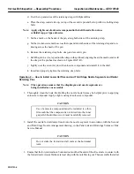
CAUTION
Do not stake the forward and aft seals at the horizontal
joint.
3. Ensure that the forward seals are bottomed out and that the ends of the aft seals are in contact with
the forward seals.
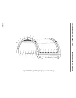
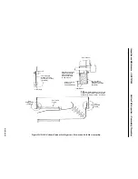
4. Assemble the axial seal strip with the notch facing out. Then assemble the radial seal strip with
the notch facing in. Appropriately stake both seals. See Figures HGP-R.3 and HGP-R.4.
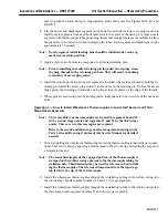
5. Lift the nozzle and diaphragm segment onto its hook fit and slide it along to its proper position.
Install nozzle segments from each horizontal joint to the bottom center line of the casing. Each
nozzle segment and diaphragm weighs approximately 35 pounds.
Note:
Nozzle segment radial retaining pins should be installed after each seg-
ment is moved into position.
6. Apply a light coat of anti-seize compound to all radial retaining pins.
7. Install the radial retaining pins as each segment is installed. Where plugs are used to hold the re-
taining pins, install the access plug so that it just bottoms on the retaining pin. Tighten the access
plugs against the retaining pins and stake each plug at four places on the edge of the threads.
8. Where pins are secured in place by holding plates, lockplates are to be used to lock the hexhead
bolts.
Operation 6 — How to Recheck First Stage Nozzle Concentricity
Note:
Assistance from your General Electric Company Apparatus and Engi-
neering Service Operation Field Service Representative is recom-
mended when making concentricity checks.
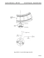
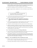
1. Take the concentricity readings as shown on Inspection Form PGS/GT-FF-6097. Record all read-
ings on the inspection form. Report readings to your General Electric Company Field Service
Representative for evaluation and disposition.
Note:
The first-stage nozzle is to be concentric with the support ring forward
outside diameter within a tolerance of 0.050 in., taking into account any
ellipticity in the first-stage nozzle assembly. Refer to the Alignment
Diagram in the Reference Drawing section of this Service Manual.
The first-stage nozzle alignment should not be changed without first
consulting your General Electric Company Field Service Representa-
tive.
Operation 7 — How to Recheck Turbine Clearances
1. All turbine clearances should be retaken per hot gas path inspection disassembly operation num-
ber eight (8) in this section and checked by your General Electric Company Field Service Repre-
sentative prior to reassembly of the turbine casing upper half.
Summary of Contents for MS6001B
Page 2: ...Gas Turbine Inspection and Maintenance GEK 107048 I 2 THIS PAGE INTENTIONALLY LEFT BLANK ...
Page 4: ...Inspection and Maintenance Note THIS PAGE INTENTIONALLY LEFT BLANK ...
Page 13: ...INSERT TAB INTRODUCTION ...
Page 14: ......
Page 25: ...INSERT TAB STANDARD PRACTICES ...
Page 26: ......
Page 87: ...INSERT TAB AUXILIARY CONTROLS SYSTEMS MAINTENANCE ...
Page 88: ......
Page 133: ...INSERT TAB SCHEDULED TURBINE MAINTENACE ...
Page 134: ......
Page 157: ...INSERT TAB COMBUSTION INSPECTION ...
Page 158: ......
Page 239: ...INSERT TAB HOT GAS PATH INSPECTION ...
Page 240: ......
Page 313: ...INSERT TAB MAJOR INSPECTION ...
Page 314: ......
Page 316: ...Inspection and Maintenance GEK 107048 Major Inspection 2 THIS PAGE INTENTIONALLY LEFT BLANK ...
Page 363: ...INSERT TAB MAINTENANCE FORMS ...
Page 364: ......


