Inspection and Maintenance — GEK 107048
Scheduled Turbine Maintenance
STM-14
The application of a monitoring program, utilizing the borescope, will allow scheduling outages and
pre-planning of parts requirements, resulting in lower maintenance costs, higher availability and reli-
ability of the gas turbine.
Service Support For Borescope Inspections
Your GE Company Field Service Representative can quote and supply technicians and equipment to
assist in setting up a program for monitoring machine condition.
Such service support also includes engineering evaluation of data and correlation of data with other
units in similar application.
Inspection Procedure
1. The gas turbine must be shutdown and the turbine wheelspace temperatures no greater than 180
°
F
(82
°
C) before the borescope is inserted.
Note:
Exposure of the borescope to higher temperatures may permanently
damage the internal glass fiber bundle.
2. For the location of borescope inspection access holes. See Figure 4-1. If a normal borescope inspec-
tion is to be done, remove the closing plugs only from those access holes (marked B.S. on turbine
cases) which are defined as Primary Inspection Access-normal Inspection. See Figure 4-1.
Note:
All casing holes on the MS-6001B with the exception of the third-stage
buckets leading edge, have an inner plug beneath the threaded plug in
the casings. Both plugs must be removed to gain access. Ensure that in-
ner plugs are correctly replaced after completing inspection.
3. When inspecting compressor blades and turbine buckets, It is necessary to rotate the rotor incremen-
tally to bring each bucket into the field of view of the borescope. This can be achieved by using the
hydraulic ratchet.
CAUTION
A lube oil supply to the rotor bearings must be maintained
during the borescope inspection.
4. A “zero” datum should be established for the rotor by marking the load coupling. This will provide
the necessary reference to determine one revolution or intermediate angular positions.
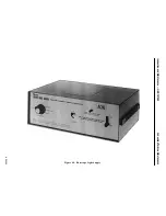
5. With the access holes open the borescope can now be inserted, the light switched ON and the light
intensity adjusted. It is recommended that the inspection commence with the compressor and proceed
through each turbine stage.
6. The procedure should consist of visually inspecting all visible stationary parts (compressor stators
and turbine nozzles) and each bucket/blade at each visible stage from root to tip including platforms
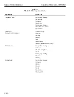
and tip seals. For inspection criteria see Table 4-1.
Summary of Contents for MS6001B
Page 2: ...Gas Turbine Inspection and Maintenance GEK 107048 I 2 THIS PAGE INTENTIONALLY LEFT BLANK ...
Page 4: ...Inspection and Maintenance Note THIS PAGE INTENTIONALLY LEFT BLANK ...
Page 13: ...INSERT TAB INTRODUCTION ...
Page 14: ......
Page 25: ...INSERT TAB STANDARD PRACTICES ...
Page 26: ......
Page 87: ...INSERT TAB AUXILIARY CONTROLS SYSTEMS MAINTENANCE ...
Page 88: ......
Page 133: ...INSERT TAB SCHEDULED TURBINE MAINTENACE ...
Page 134: ......
Page 157: ...INSERT TAB COMBUSTION INSPECTION ...
Page 158: ......
Page 239: ...INSERT TAB HOT GAS PATH INSPECTION ...
Page 240: ......
Page 313: ...INSERT TAB MAJOR INSPECTION ...
Page 314: ......
Page 316: ...Inspection and Maintenance GEK 107048 Major Inspection 2 THIS PAGE INTENTIONALLY LEFT BLANK ...
Page 363: ...INSERT TAB MAINTENANCE FORMS ...
Page 364: ......


