Major Inspection — Inspection Procedures
Inspection and Maintenance — GEK 107048
MI-I-3
2. Report any discrepancies to your General Electric Company Field Service Representative.
Operation 7 — How to Inspect Sleeve Bearings and Thrust Bearings
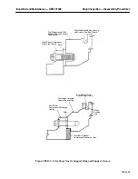
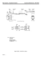
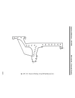
1. Assemble rotor support and lever in exhaust frame and under the shaft to raise the shaft for the
removal of the lower half number two bearing liner. See Figure MI-I.1.
2. Mount a dial indicator at the bearing liner centerline, using the rotor support lever, raise the shaft
0.014 in. maximum and block into position with rotor support lever threaded bolt.
CAUTION
Take appropriate precautions to assure that the shaft is not
damaged by the rotor support lever when raising the shaft.
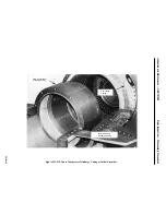
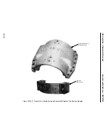
3. Roll out the lower half number two bearing liner.
4. Place protective covering over the bearing housing to protect the rotor bearing journal and keep
foreign matter out of the housing.
5. Inspect journal bearing babbitt surface for cracks, wiped babbitt, scoring, foreign material, pit-
ting, spalling, and excessive or abnormal wear patterns. Cracked and chipped babbitt can general-
ly be repaired in an approved General Electric Company Repair Facility, if the damage is not ex-
cessive. It is apparent, of course, that cause of the damage within the unit must be eliminated to
prevent further cracking and chipping.
Note:
Lube oil contamination with dirt or metal particles will result in scored
surfaces of rotor journals, thrust faces, bearing liners, and thrust bear-
ings. A characteristic of particle scored bearings is the frequent occur-
rence of full circumferential score marks on the rotating members. On
journal and thrust bearing liners the score marks will frequently ex-
tend through the circumferential length of the pressure zone.
Although any damage to bearing surfaces will result in a theoretical
performance degradation, certain practical limits can be set within
which the function of the bearing is not compromised beyond the de-
gree normally expected from manufacturing variabilities.
A restricted number of circumferential grooves can therefore be toler-
ated in the bearing area provided the total volume of the groove (which
acts as a partial oil short-circuit) is limited. The following are accep-
tance limits which can be used as an acceptance guide for used bearing
components.
6. Some scratching or pitting will always occur on babbitted bearing surfaces during normal opera-
tion because of impurities which accumulate in the lubricating oil system. Scratches or pits that
are not over 0.005 in. deep, pits that are not over 0.100 in. in diameter and pits or scratches do
not extend axially more than 1/3 of the bearing length, (axial scratches and pit formations must
be circumferentially at least 45 degrees apart), are acceptable. Raised metal is not allowed.
Summary of Contents for MS6001B
Page 2: ...Gas Turbine Inspection and Maintenance GEK 107048 I 2 THIS PAGE INTENTIONALLY LEFT BLANK ...
Page 4: ...Inspection and Maintenance Note THIS PAGE INTENTIONALLY LEFT BLANK ...
Page 13: ...INSERT TAB INTRODUCTION ...
Page 14: ......
Page 25: ...INSERT TAB STANDARD PRACTICES ...
Page 26: ......
Page 87: ...INSERT TAB AUXILIARY CONTROLS SYSTEMS MAINTENANCE ...
Page 88: ......
Page 133: ...INSERT TAB SCHEDULED TURBINE MAINTENACE ...
Page 134: ......
Page 157: ...INSERT TAB COMBUSTION INSPECTION ...
Page 158: ......
Page 239: ...INSERT TAB HOT GAS PATH INSPECTION ...
Page 240: ......
Page 313: ...INSERT TAB MAJOR INSPECTION ...
Page 314: ......
Page 316: ...Inspection and Maintenance GEK 107048 Major Inspection 2 THIS PAGE INTENTIONALLY LEFT BLANK ...
Page 363: ...INSERT TAB MAINTENANCE FORMS ...
Page 364: ......

