Inspection and Maintenance — GEK 107048
Major Inspection — Disassembly Procedures
MI-D-2
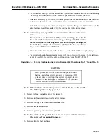
CAUTION
The generator field and load gear do not have a thrust bear-
ing; therefore, there will be a tendency for the rotor to
“walk” axially.
c. The “walking” can be compensated for by using two dial indicators. One indicator will be
mounted on the rotating flange and will measure the actual face run-out. The other indicator
will mount to the stationary flange and it will see mechanical face run-out plus axial move-
ment, if any. Both indicators must be read simultaneously.
Note:
All readings must repeat three consecutive times to be considered
accurate.
The indicators should return to “0” (corrected reading of zero for the
face and rim indicators) when returning to the top end of the vertical
mark. If they do not, check tightness of set-up and repeat the readings.
Refer to the Basic Alignment Instructions (Field) in the Reference
Drawings section of this Service Manual.
d. Record coupling alignment readings on Inspection Form PGS/GT-FF-6115. Refer to Basic
Alignment Instructions (Field) in the Reference Drawing section of this Service Manual.
6. Remove and inspect accessory coupling.
a. Matchmark the accessory gear to the coupling sleeve, both sleeves to the coupling shaft, and
the turbine rotor to the coupling sleeve.
b. Set up a dial indicator and check end float and radial clearance.
c. Drain the oil, and unbolt the sleeves. Remove the coupling from the unit.
d. Clean the sleeves and teeth.
e. Record the radial clearance, end thrust, and tooth condition on Inspection Form PGS/
GT-FF-6113.
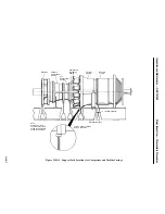
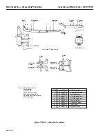
7. Check turbine to accessory gear alignment.
Note:
The method described utilizes an alignment fixture supplied in the tur-
bine tool kit, in place of the coupling shaft.
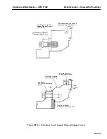
a. Using a felt tipped pen, mark two lines (one vertical, the other horizontal) across the face of
the turbine coupling. The lines should intersect at the center of the coupling face.
b. Tightly attach the alignment fixture to the accessory gear coupling flange.
c. Place dial indicator to read from the alignment fixture to the face of the turbine coupling.
Note:
Using a piece of 2 x 4 mounted behind the accessory gear drive coupling
flange, apply just enough force to take up the end float (thrust) on the
shaft when taking the face readings.
Summary of Contents for MS6001B
Page 2: ...Gas Turbine Inspection and Maintenance GEK 107048 I 2 THIS PAGE INTENTIONALLY LEFT BLANK ...
Page 4: ...Inspection and Maintenance Note THIS PAGE INTENTIONALLY LEFT BLANK ...
Page 13: ...INSERT TAB INTRODUCTION ...
Page 14: ......
Page 25: ...INSERT TAB STANDARD PRACTICES ...
Page 26: ......
Page 87: ...INSERT TAB AUXILIARY CONTROLS SYSTEMS MAINTENANCE ...
Page 88: ......
Page 133: ...INSERT TAB SCHEDULED TURBINE MAINTENACE ...
Page 134: ......
Page 157: ...INSERT TAB COMBUSTION INSPECTION ...
Page 158: ......
Page 239: ...INSERT TAB HOT GAS PATH INSPECTION ...
Page 240: ......
Page 313: ...INSERT TAB MAJOR INSPECTION ...
Page 314: ......
Page 316: ...Inspection and Maintenance GEK 107048 Major Inspection 2 THIS PAGE INTENTIONALLY LEFT BLANK ...
Page 363: ...INSERT TAB MAINTENANCE FORMS ...
Page 364: ......

