Hot Gas Path Inspection — Inspection Procedures
Inspection and Maintenance — GEK 107048
HGP-I-19
Second/Third Stage Shrouds
Radial cracks in the shroud seal teeth are self-limiting and are not expected to propagate into the
shroud block itself.
All unsound portions of the shroud, including circumferential cracks that may link with radial cracks
and thinned sections, should be blended back to sound metal and reinspected for further cracking.
Most seal tooth distortion is not expected to affect unit performance. Attempts to straighten or other-
wise repair distorted teeth may lead to cracking and requirements to grind out sections of the tooth,
which will affect unit performance. Therefore, provided the distorted sections are not cracked or ex-
cessively thinned, they should be left as is.
When replacing shroud blocks, they should be replaced in complete sets along with new seals. It is
extremely difficult to replace individual blocks due to the downstream deflection of all the blocks over
time. All borescope hole plugs, clearance hole plug and straight pins should be inspected for cracking
and bending. Replace those that are damaged.
Note:
When replacing the first stage shrouds, it will be necessary to drill the
holes for the pins and plugs. The blocks will have to be installed in the
turbine to properly locate where holes are to be drilled. Proper clear-
ance between shrouds is necessary. Refer to the turbine case arrange-
ment drawing ML0705 for all dimensions. When the blocks are re-
moved for drilling it will be necessary to also locate and drill the cooling
holes. These holes must intersect the shroud pin holes. This is also
shown on the turbine case arrangement drawing.
Operation 5 — How to Inspect Second and Third Stage Nozzle Diaphragms
1. Clean nozzle assembly by blasting with aluminum oxide 220 grit or finer as detailed in the Stan-
dard Practices section, Gas Turbine Cleaning section in this Service Manual.
2. Check for cracks using fluorescent penetrant. Zyglo ZL22A is preferred. Record findings on In-
spection Form PGS/GT-FF-6100 and PGS/GT-FF-6103.
3. Make a visual inspection for foreign object damage, burning, corrosion, erosion, and excessive
deposit buildup. Report findings on Inspection Form PGS/GT-FF-6100 and PGS/GT-FF-6103.
Note:
Each diaphragm segment is normally removed along with the nozzle
segment. The diaphragm segments are not normally separated in the
field to make checks.
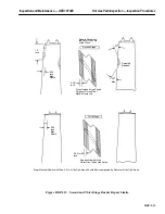
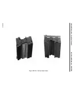
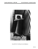
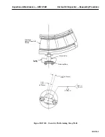
4. Make a visual inspection of all diaphragm seal teeth, first-stage aft wheelspace seals, second-stage
forward wheelspace seals and second-stage aft and third-stage forward wheelspace seals. See Fig-
ure HGP-I.17 and HGP-I.18.
5. Note the condition on Inspection Form PGS/GT-FF-6100 and PGS/GT-FF-6103.
6. Inspect diaphragm teeth as follows: Observe the worst rubbed tooth and measure its tooth height.
Compare this measurement to the height of the tooth on the diaphragm segment previously posi-
tioned at the horizontal joint where the tolerance of the gap 1PL and 1PH or 2PL and 2PH (see
Summary of Contents for MS6001B
Page 2: ...Gas Turbine Inspection and Maintenance GEK 107048 I 2 THIS PAGE INTENTIONALLY LEFT BLANK ...
Page 4: ...Inspection and Maintenance Note THIS PAGE INTENTIONALLY LEFT BLANK ...
Page 13: ...INSERT TAB INTRODUCTION ...
Page 14: ......
Page 25: ...INSERT TAB STANDARD PRACTICES ...
Page 26: ......
Page 87: ...INSERT TAB AUXILIARY CONTROLS SYSTEMS MAINTENANCE ...
Page 88: ......
Page 133: ...INSERT TAB SCHEDULED TURBINE MAINTENACE ...
Page 134: ......
Page 157: ...INSERT TAB COMBUSTION INSPECTION ...
Page 158: ......
Page 239: ...INSERT TAB HOT GAS PATH INSPECTION ...
Page 240: ......
Page 313: ...INSERT TAB MAJOR INSPECTION ...
Page 314: ......
Page 316: ...Inspection and Maintenance GEK 107048 Major Inspection 2 THIS PAGE INTENTIONALLY LEFT BLANK ...
Page 363: ...INSERT TAB MAINTENANCE FORMS ...
Page 364: ......


