Major Inspection — Disassembly Procedures
Inspection and Maintenance — GEK 107048
MI-D-11
CAUTION
The forward compressor upper half casing weighs ap-
proximately 1775 pounds. The combined one piece upper
half casing (forward and aft) weighs 3100 pounds.
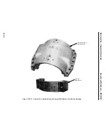
Operation 10 — How to Remove Upper Half Inlet Casing
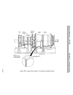
1. Disconnect the wiring to the magnetic pickup located in the inlet and number one bearing area.
2. Unbolt and remove the magnetic pickup ring from the front of the inlet and number one bearing.
3. Remove upper half inlet casing horizontal joint bolting.
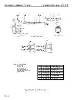
CAUTION
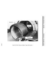
There are twelve point bolts located in the air passage of
the inlet casing which must be removed. See Figure
MI-D.3.
4. Remove the horizontal flange body bound bolts located on the forward inlet casing bellmouth.
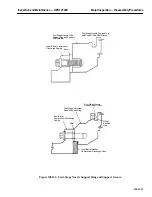
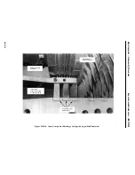
5. Adjust the inlet guide vane control ring support plate bolts so that the lower half inlet guide vane
control ring does not drop. See Figure MI-D.4.
6. Unbolt the inlet guide vane control ring and secure to the upper half casing.
CAUTION
Do not lift the inlet casing by using the inlet flange spread-
er bars. These are dampening struts and are not to be used
for lifting attachments.
7. Rig lifting cables, chainfall and blocks as shown on the Weights and Center of Gravity drawing
in the Reference Drawing Section of this Service Manual to the upper half inlet casing.
CAUTION
The upper half inlet casing weighs approximately 5500
pounds.
8. Use the chainfall to initially lift the inlet casing, continue to lift the casing straight up and clear
of the unit. Use suitable blocking, stand the inlet casing in a vertical position.
9. Roll lower half rub ring around the shaft and remove.
Summary of Contents for MS6001B
Page 2: ...Gas Turbine Inspection and Maintenance GEK 107048 I 2 THIS PAGE INTENTIONALLY LEFT BLANK ...
Page 4: ...Inspection and Maintenance Note THIS PAGE INTENTIONALLY LEFT BLANK ...
Page 13: ...INSERT TAB INTRODUCTION ...
Page 14: ......
Page 25: ...INSERT TAB STANDARD PRACTICES ...
Page 26: ......
Page 87: ...INSERT TAB AUXILIARY CONTROLS SYSTEMS MAINTENANCE ...
Page 88: ......
Page 133: ...INSERT TAB SCHEDULED TURBINE MAINTENACE ...
Page 134: ......
Page 157: ...INSERT TAB COMBUSTION INSPECTION ...
Page 158: ......
Page 239: ...INSERT TAB HOT GAS PATH INSPECTION ...
Page 240: ......
Page 313: ...INSERT TAB MAJOR INSPECTION ...
Page 314: ......
Page 316: ...Inspection and Maintenance GEK 107048 Major Inspection 2 THIS PAGE INTENTIONALLY LEFT BLANK ...
Page 363: ...INSERT TAB MAINTENANCE FORMS ...
Page 364: ......


