


Major Inspection — Reassembly Procedures
Inspection and Maintenance — GEK 107048
MI-R-1
III. Reassembly Procedures (Major Inspection)
For MS-6001B DLN-1 Equipped Machines
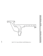
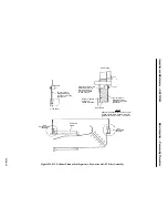
Operation 1 — How to Reassemble Sleeve Bearings, Thrust Bearings, Upper Half Bearing
Housings and Exhaust Hood Baffle
CAUTION
Prior to reassembly of thrust bearings and bearings, care-
fully check the housings and bearing areas to assure all
tools, parts and debris have been removed and the hous-
ings are thoroughly clean before closing.
Note:
Use a very light coating of clean, turbine oil only during assembly of the
thrust bearings and bearings.
1. Reassemble the thrust bearings in the reverse manner as they were disassembled. Roll in the inac-
tive thrust lower and upper halves and position the anti-rotation pin.
2. Assemble the inactive thrust shims into the bearing cavity.
3. With inactive thrust bearing and shims assembled in place thrust the rotor up against the inactive
thrust bearing to allow room to assemble the active thrust bearing and shims.
4. Roll in the lower half of the active thrust bearing base ring, installing the thrust pads as it enters
the lower housing. Set the upper half of the base ring on the active thrust bearing and install the
upper half thrust pads. Roll the assembly around to position the anti-rotation key. After the active
thrust bearing is assembled, slide the rotor position shim into place behind the active thrust bear-
ing.
5. Check the rotor journal and number one bearing housing lower half for cleanliness.
6. Assemble the upper half bearing liner to the upper half bearing housing or to the lower half bear-
ing liner, whichever is applicable.
7. Clean and deburr the mating joints of the number one bearing housing. Apply a light coating of
joint sealant to the lower horizontal joint. Refer to the Standard Practices section for the recom-
mended joint sealant.
8. Rig, using a chainfall, and lift the upper half housing into position on the lower half. Apply a coat-
ing of anti-seize compound to dowels and bolting. Install bolting and torque bolts alternately from
the center of each horizontal joint outward.
9. Reconnect all instrumentation and tubing which was removed.
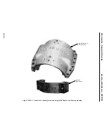
10. Assemble the upper half exhaust air cone (baffle) to the lower half in the number two bearing area.
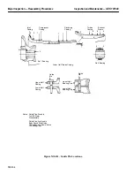
11. Check the rotor journal and the number two bearing housing for cleanliness, clean and deburr
bearing strap mating surfaces and number two bearing housing horizontal joints.
Summary of Contents for MS6001B
Page 2: ...Gas Turbine Inspection and Maintenance GEK 107048 I 2 THIS PAGE INTENTIONALLY LEFT BLANK ...
Page 4: ...Inspection and Maintenance Note THIS PAGE INTENTIONALLY LEFT BLANK ...
Page 13: ...INSERT TAB INTRODUCTION ...
Page 14: ......
Page 25: ...INSERT TAB STANDARD PRACTICES ...
Page 26: ......
Page 87: ...INSERT TAB AUXILIARY CONTROLS SYSTEMS MAINTENANCE ...
Page 88: ......
Page 133: ...INSERT TAB SCHEDULED TURBINE MAINTENACE ...
Page 134: ......
Page 157: ...INSERT TAB COMBUSTION INSPECTION ...
Page 158: ......
Page 239: ...INSERT TAB HOT GAS PATH INSPECTION ...
Page 240: ......
Page 313: ...INSERT TAB MAJOR INSPECTION ...
Page 314: ......
Page 316: ...Inspection and Maintenance GEK 107048 Major Inspection 2 THIS PAGE INTENTIONALLY LEFT BLANK ...
Page 363: ...INSERT TAB MAINTENANCE FORMS ...
Page 364: ......