background image

Combustion Inspection — Inspection Procedures

Inspection and Maintenance — GEK 107048

CI-I-7

**WARNING**

Cleaning solutions are extremely caustic. Wear pro-
tective clothing, gloves and face shield to prevent con-
tact with skin or eyes. If solution contacts skin or eyes,
irrigate thoroughly with clean water and immediately
obtain medical aid.

CAUTION

Depending on the cleaning solution, a rinse solution is fre-
quently required. Follow the manufacturer’s recommen-
dations for cleaning solution being used.

4. Remove the parts from the cleaning solution, and spray with water and steam to knock off loosened

carbon.

5. Rinse the parts, and coat them with either clean fuel oil or light machine oil.

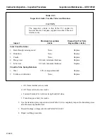
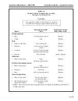
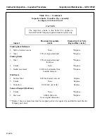
6. Visually inspect all parts, keeping in mind that the contact surfaces of the fuel nozzle parts are ma-

chined to a fine finish so the flow rates of fuel oil or gas and atomizing air through the nozzle as-
sembly will be within specified limits. When inspecting parts, make sure there are no dents, burrs
or nicks on any surfaces which will result in an interference on reassembly. These types of defects
could affect fuel or air flow.

Special attention should be given to the condition of the swirl slots in the fuel nozzle pilot, and
the surfaces with which the nozzle pilot are in contact. If the swirl slots show any indication of
crushing, galling or erosion, or if the surfaces with which they are in contact are not flat and
smooth, the parts must be replaced.

CAUTION

Do not attempt to remachine damaged parts. This can
cause irregular fuel flow, erratic combustion system oper-
ation, and subsequent turbine damage.

7. Inspect the outer gas swirl tip for wear at the area normally in contact with the combustion liner

cap/collar. If wear in this area is 0.030 inch or more, contact your General Electric Company Field
Service Representative for information concerning repair of the outer gas swirl tip diameter.

8. Inspect the outer tip assembly to determine if parts have been adversely affected by erosion. In-

spect the condition of the gas fuel holes in the gas swirl tip assembly. They should be sharp, not
rounded or burred. If the inlet edges of the gas holes have eroded or have been rounded or nicked,
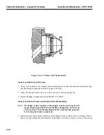
they will affect the flow test. Figure CI-I.3 shows the components of the typical fuel nozzle.

Summary of Contents for MS6001B

Page 1: ...GE Power Systems Gas Turbine GEK 107048 Rev 0 11 98 Inspection and Maintenance Instructions For MS 6001B Gas Turbines With DLN 1 Combustion Systems Gas Only ...

Page 2: ...Gas Turbine Inspection and Maintenance GEK 107048 I 2 THIS PAGE INTENTIONALLY LEFT BLANK ...

Page 3: ...e been reformatted to separate the Disassembly Inspection and Reassembly Operations for each inspection The figure numbers and page numbers have also been revised to follow this format A D preceding a figure or page number is used for the Disassembly section an I is used for the Inspection section and an R is used for the Reassembly section ...

Page 4: ...Inspection and Maintenance Note THIS PAGE INTENTIONALLY LEFT BLANK ...

Page 5: ...ering SP 41 Returning Turbine Parts for Repair Replacement SP 41 Maintenance Parts Recommendations SP 41 Combustion Inspection SP 42 Hot Gas Path Inspection SP 45 Major Inspection SP 50 AUXILIARY AND CONTROLS SYSTEM MAINTENANCE Index Index Periodic Inspection Schedule ACSM 2 Index Index Inspection and Maintenance Procedures IMP 1 SCHEDULED TURBINE MAINTENANCE Running Inspections STM 1 Housekeeping...

Page 6: ...Maintenance GEK 107048 Table of Contents ii MAJOR INSPECTION Index Index Disassembly MI D 1 Inspection MI I 1 Reassembly MI R 1 MAINTENANCE INSPECTION FORMS List of all MS 6001B DLN 1 Inspection Forms MF 1 Forms MF 5 ...

Page 7: ...I D 6 CI D 6 Swagelok Fitting With Stop Collar CI D 7 CI D 7 False Start Drain Piping CI D 8 CI D 8 Secondary Fuel Nozzle CI D 10 CI D 9 Suggested Storage and Moving Rack For Secondary Fuel Nozzles CI D 11 CI D 10 Spark Plug Assembly CI D 12 CI D 11 End Cover With Primary Nozzles and Guide Pins CI D 15 CI D 12 Typical Multi Nozzle Assembly Moving and Storage Fixture CI D 15 CI D 13 Crossfire Tube ...

Page 8: ...and Flow Sleeve Assembly CI R 12 CI R 11 Outer Combustion Casing Alignment Pin CI R 13 CI R 12 Outer Crossfire Tube CI R 15 CI R 13 Crossfire Tube Assembly CI R 16 CI R 14 Spark Plug Assembly CI R 17 CI R 15 Primary Flame Detector CI R 18 HGP D 1 Rotor Position Probe HGP D 4 HGP D 2 Support Jack Locations for Compressor and Turbine Casings HGP D 6 HGP D 3 Turbine Casing Rigging for Removal HGP D 8...

Page 9: ...nstallation HGP R 15 HGP R 7 Typical Bolt Tightening Sequence for Unit Casings HGP R 16 HGP R 8 Exhaust Plenum Seal Segments Forward and Aft Sides Assembly HGP R 19 MI D 1 Support Jack Locations for Compressor and Turbine Casings MI D 7 MI D 2 Guide Pin Locations MI D 10 MI D 3 Twelve Point Bolts in Inlet Casing MI D 12 MI D 4 Inlet Guide Vane Ring Support Plate and Locking Bolt MI D 13 MI D 5 Fir...

Page 10: ...SP 6 4 1 MS 6001B DLN 1 Inspection Criteria STM 16 4 2 MS 6001B DLN 1 Borescope Access Hole Locations STM 17 CI 1 Recommended Cleaning Compounds CI I 6 CI 2 Inspection Limits MS 6001B DLN 1 Liners CI I 14 CI 3 Inspection Limits Crossfire Tubes and Retainers CI I 18 CI 4 Inspection Limits Transition Piece Assembly CI I 19 CI 5 Inspection Limits for Flow Sleeves CI I 24 CI 6 Inspection Limits Spark ...

Page 11: ...h could result in injury to personnel or loss of life if not followed correctly SAFETY This publication is designed to provide safe procedures and processes for accomplishing the maintenance instructions described herein It is important therefore that the warn ings cautions and notes in these procedures be thoroughly understood and observed by the personnel performing maintenance Changes or additi...

Page 12: ...Inspection and Maintenance Notes Cautions and Warnings viii THIS PAGE INTENTIONALLY LEFT BLANK ...

Page 13: ...INSERT TAB INTRODUCTION ...

Page 14: ......

Page 15: ...t and corrosive atmosphere Prior to scheduled inspections or taking operating data clean the compressor per the gas turbine compressor cleaning procedure in the Water Wash Cleaning Tab section of Volume II Before and after any inspection a complete set of operating data including vibration readings should be taken and recorded for reference A re cord of the inspections made and the maintenance wor...

Page 16: ...e load cycle of the gas turbine up to its continuous rating will have little effect on parts lives provided it does not require frequent and rapid load changes Environment The condition of the inlet air to the gas turbine can have a significant effect on maintenance costs and intervals if it is either abrasive or corrosive If abrasives are in the inlet air e g as from sand storms careful attention...

Page 17: ...e running inspection is performed during start up and while the unit is operating This inspection indicates the general condition of the gas turbine unit and its associated equipment The shutdown inspection is performed while the unit is at a standstill The shutdown inspec tions include Combustion Hot Gas Path and Major inspections These latter inspections require disassembly of the turbine in var...

Page 18: ...ice the re moved liners and transition pieces can be bench inspected and repaired if necessary by competent service personnel or off site at a qualified service facility Off site cleaning inspection and repair of the liners and transition pieces is recommended since this activity can best be performed where specialized equipment and fixtures are available The removed fuel nozzles can be cleaned an...

Page 19: ...on should be exercised to ensure that the inlet guide vane controls have been rendered inoper able during measurement and inspection Failure to do so could result in injury to personnel With the gas turbine shut down and the inlet guide vanes secured in the normally open position for loaded operation 84 degrees in most instances use a dial indicator to measure motion normal to the vane chord Posit...

Page 20: ... there are periods of heavy demand where certain parts may not be readily available for planned inspections It is strongly recommended that high probability parts be available on site prior to the start of inspections Spare and Renewal Parts sales personnel have responsibility for customer contact to advise scheduling of maintenance parts and identify additional parts needs Local Spare and Renewal...

Page 21: ...ntenance GEK 107048 Introduction I 7 Type of Fuel Starting Frequency Load Cycle Environment Maintenance Practices Figure 1 1 Parts Life Factors Figure 1 2 Effect of Fuel Natural Gas 4 3 2 1 0 Fuel Type Maintenance Factor ...

Page 22: ...Factor TYPE OF 8 HOUR INSPECTION SHIFTS Combustion 8 Hot Gas Path 12 Major 25 Assumptions No Repair Time Replacement Only All Parts Available All Necessary Tools Available Crew With Average Trade Skill Flange To Flange Turbine Only Inspection Has Been Pre Planned Figure 1 4 Maintenance Inspections Model Series 6000 Estimated Outage Requirements ...

Page 23: ... Combustion Turbine Exhaust 0901 1604 1314 1313 0546 1612 0812 0801 0811 0802 1301 1302 0803 0513 1214 1121 0703 0701 0804 0710 0702 1403 1401 1402 1409 0706 1502 1625 1319 Major Inspection Hot Gas Path Inspection Combustion Inspection Figure 1 5 Types of Shutdown Inspections ...

Page 24: ...tor to measure motion normal to the vane cord Position the indicator to read as close to the vane inner button as possible 3 Deflect vane in a tangential direc tion perpendicular to the air flow direction to both sides of the bushing clearance and record full dial indicator reading Airflow Direction VIGV Bushing VIGV in Fully Open Position Dial Indicator 84 1 2 3 ...

Page 25: ...INSERT TAB STANDARD PRACTICES ...

Page 26: ......

Page 27: ...n while this sys tem is disabled WARNING Fire suppressant in a concentration sufficient to extin guish fire creates an atmosphere that will not support life It is extremely hazardous to enter the compart ment after the CO2 system has discharged Anyone rendered unconscious by fire suppressant should be rescued as quickly as possible and revived immediately with artificial respiration or by mouth to...

Page 28: ...arters Marks A Lot black or blue Dixon Company black or blue Everhard Faber 7500 Wa ter Color black Dykem Company dark blue Dykem DSL light blue Dykem DMP high spot blue Dykem 107 Joseph Dixon lead free yellow lumber crayons Wallace Pencil Company 800 black marker Machine Manufacturing Company Marco S 1141 black and Marco S 1141 white are rec ommended and approved markers Nickel base alloys are su...

Page 29: ...o apply on vertical flange faces of the top halves of outer casings that may be subject to removal for maintenance Note This usage must be restricted to a thin film such that the compound is not forced into the inner gas path Should this occur it must where possible be carefully removed b Do not apply anti seize compound to pipe threads or bolting threads internal to oil or water tanks 18 Sealing ...

Page 30: ...on the flanges Use anti seize compound on the bolts Tighten the bolts in three stages on alternately opposite bolts 21 Bolt and Stud Torquing a Before torquing remove foreign matter from bolt nut and bolting surfaces b Apply anti seize compound to bolt and nut threads and bearing surfaces c Tighten bolt or nut to be sure threads are free then back off until free from surface Snug against surface a...

Page 31: ... 13 10 32 17 19 15 17 0 250 20 60 72 48 60 0 375 10 204 228 164 186 0 500 13 492 552 392 447 0 625 11 815 912 720 816 0 750 11 1761 1980 147 165 1550 1775 129 147 0 875 9 200 222 170 200 1 00 8 348 395 300 348 1 25 8 648 732 564 648 1 50 8 1175 1320 1030 1175 OVER 1 50 ELONGATION PER INCH OF EFFECTIVE LENGTH 0 0013 0 0015 SEE ELONGATION VALUES ON TABLE 2 2 Figure 2 1 Typical Flange Joint Makeup Ed...

Page 32: ...58 5 50 0 0082 0 0064 6 00 0 0090 0 0070 6 50 0 100 0 0075 7 00 0 0105 0 0080 7 50 0 0110 0 0087 8 00 0 0120 0 0093 8 50 0 0130 0 0098 9 00 0 0135 0 0100 9 50 0 0140 0 0110 10 00 0 0150 0 0116 10 50 0 0157 0 0121 11 00 0 0166 0 0130 11 50 0 0177 0 0133 12 00 0 0189 0 0140 BOLT OR STUD IN BLIND HOLE A ANGLE OF ROT ELONGATION 4 0 001 8 0 002 12 0 003 16 0 004 20 0 005 39 0 010 60 0 015 Bolt and Stud...

Page 33: ... hardening adhesive plastic compound 158A2557P1 Petrolatum Used on compartment door gaskets to prevent sticking 118A449P4 Atlantic Richfield Gulf Oil Humble Oil or equivalent RTV102 Adhesive Silicone rubber sealant white paste GE Co RTV106 Adhesive Silicone rubber sealant Good for high temperature areas red paste GE Co Locktite Pipe Sealant with Teflon Used on all pipe thread joints 118D5700 Lockt...

Page 34: ...le for outdoor environments 158A7228P1 3M2121 Strip Caulk Unit lagging soft nonhardening sealer 156A1563P2 or P1 Moreland Chemical Co Sodium Silicote Adhesive Heavy grade adhesive paste 239A5612P19 Vimasco 136 Canvas lagging adhesive 248A5660P1 Zyglo ZL22 Fluorescent penetrant for crack check From Magnaflux Corporation Chicago Ill Plus Gas Formula A Dismantling Fluid Penetrating oil From Dockrell ...

Page 35: ...Ease N5000 Fel Pro products and Teutonic Power Tool s 0505 as acceptable anti seize compounds Although the four compounds listed above are recommended use of any other anti seize compounds is acceptable provided they meet the guidelines given in Table 2 3 A number of other commercially available compounds have been considered as replacements However many have low melting point elements such as alu...

Page 36: ...ubricants listed do not exclude comparable products from other oil companies Should the purchaser wish to use an alternate lubricant not mentioned or recommended by the component manufacturer approval must be requested from the component manufacturer not the GE Company The use of lubricant grades other than those recommended should be first approved by the GE Company WARNING Motor shaft must be st...

Page 37: ...oint 2 1 2 inch drive sockets 1 inch 2 1 2 inch drive sockets 1 1 8 inch 2 1 inch drive sockets 1 1 2 inch 2 1 inch drive sockets 1 7 8 inch 2 1 inch drive sockets 2 1 4 inch 1 set box wrenches open end to 2 inches 1 set box wrenches 12 point 1 1 8 inch to 2 1 4 inch Slugging wrenches 2 each 1 1 2 1 7 8 2 1 4 inches Slugging wrenches 12 point 1 1 2 1 7 8 2 1 4 inches Miscellaneous 2 6 inch adjusta...

Page 38: ... 1 4 1 1 2 x 8 thd Impact wrenches 1 1 2 inch drive with sockets 2 3 4 inch drive with sockets 1 1 inch drive with sockets Electric or air drill with chuck to 1 2 inch with bits 4 50 foot air hoses with 1 2 inch whips Air grinder with grinding wheels Dial indicators 1 Starrett Last Word 1 Starrett Universal 2 0 to 1 inch indicator plus magnetic bases arms and swivels Micrometers 1 0 1 outside 1 0 ...

Page 39: ... impact wrenches Oxyacetylene cutting outfit Engine driven welder Chain hoists 1 10 ton 1 8 ton 1 3 ton Comealong 2 1 2 ton 2 1 1 2 ton 2 3 1 2 ton Eyebolts 8 1 2 13 shouldered 8 5 8 11 shouldered 8 3 4 10 shouldered 4 1 8 shouldered 2 1 1 2 6 shouldered Eyebolts special 4 1 2 13 x 12 inches 4 5 8 11 x 12 inches Shackles 4 3 16 inch pin 4 1 4 inch pin 4 3 8 inch pin 4 1 2 inch pin 4 3 4 inch pin S...

Page 40: ...seize 13 cans joint compound 3 rolls masking tape 6 rolls duct tape 14 marking pens lead and sulfur free Carter s Marks A Lot or equivalent see Standard Practices General Section 100 wiping cloths 2 tubes Teflon thread sealant liquid Barrel of solvent Weather stripping glue Miscellaneous items 100 ft work lights Fire extinguishers 100 ft extension cords Tote boxes Ladders Tie on tags Gloves Tape w...

Page 41: ...isassembly and Reassembly of Turbine Casing 4 2 5 Jacking Bolt For Jacking Number One Bearing Forward and Aft Compressor Casing 0 750 10 x 4 00 4 2 6 Jacking Bolt For Jacking Compressor Discharge Casing 1 50 8 x 5 00 6 2 6 Jacking Bolt For Jacking Compressor Discharge Casing 1 50 8 x 3 25 6 2 6 Jacking Bolt For Jacking Turbine Casing 1 750 8 x 6 00 4 2 6 Jacking Bolt For Jacking Turbine Casing 1 7...

Page 42: ...Turbine Casing and Exhaust Frame Removal and Installation 11 2 20 Hook Clevis Foundry Used For Turbine Casing and Exhaust Frame Removal and Installation 4 2 21 Ratchet Gear Come Along Used For Turbine Casing and Exhaust Frame Removal and Installation 2 2 22 Link Connection Used For Turbine Casing and Exhaust Frame Removal and Installation 4 2 23 Hook Clevis Grab Used For Turbine Casing and Exhaust...

Page 43: ...d for Flushing Hydraulic Control Oil Lines 1 2 35 Pliers Hose Clamp Atomizing Air Compressor Used for Removing the Retaining Ring From the Atomizing Air Compressor Quill Shaft 1 2 36 Tool Insertion and Extraction Used for Disassembly and Reassembly of Cable Connections 1 2 37 Tubing Plastic Used for Bleeding Air From Fuel System Filters 1 2 38 Insert Tubing Used with Plastic Tubing and Male Connec...

Page 44: ...Inspection and Maintenance GEK 107048 Standard Practices SP 18 Figure 2 2 Guide Pin Inlet Casing Figure 2 3 Guide Pin Compressor Casing ...

Page 45: ...Standard Practices Inspection and Maintenance GEK 107048 SP 19 Figure 2 4 Guide Pin Bearings and Exhaust Frame Figure 2 5 Guide Pin Compressor Discharge and Turbine Casing ...

Page 46: ...Inspection and Maintenance GEK 107048 Standard Practices SP 20 Figure 2 6 Typical Jacking Bolt Unit Casings Figure 2 7 Jacking Rod Number Two Bearing Disassembly ...

Page 47: ...Standard Practices Inspection and Maintenance GEK 107048 SP 21 Figure 2 8 Fixture Arrangement Number Two Bearing and Coupling ...

Page 48: ...Inspection and Maintenance GEK 107048 Standard Practices SP 22 Figure 2 9 Fuel Nozzle Wrenches Figure 2 10 Tool Alignment Pin 750 10Unc 2A 750 10Unc 2A ...

Page 49: ...ection and Maintenance GEK 107048 SP 23 Figure 2 11 Tool Transition Piece Side Clearance Approx 10 0 53 0 36 0 200 Typ Approx 5 1 2 1 2 10 160 090 70 200 TYP 3 16 thru Hole Figure 2 12 Tool Transition Piece First Stage Nozzle ...

Page 50: ...Inspection and Maintenance GEK 107048 Standard Practices SP 24 Figure 2 13 Alignment Fixture Figure 2 14 Staking Tool Fuel Nozzle ...

Page 51: ...Standard Practices Inspection and Maintenance GEK 107048 SP 25 Figure 2 15 Combustion Liner Puller Jacking Bolt typ 3 plc s ...

Page 52: ...Inspection and Maintenance GEK 107048 Standard Practices SP 26 Figure 2 16 Rail Fabrication Hoist Figure 2 17 Lifting Beam ...

Page 53: ...Standard Practices Inspection and Maintenance GEK 107048 SP 27 Figure 2 18 Cable Sling Figure 2 19 Trolley Hoist ...

Page 54: ...Inspection and Maintenance GEK 107048 Standard Practices SP 28 Figure 2 20 Typical Anchor Shackle Figure 2 21 Clevis Hook Foundry ...

Page 55: ...Standard Practices Inspection and Maintenance GEK 107048 SP 29 Figure 2 22 Ratchet Gear Come Along Figure 2 23 Connection Link ...

Page 56: ...Inspection and Maintenance GEK 107048 Standard Practices SP 30 Figure 2 24 Clevis Hook Grab Figure 2 25 Chain Sling ...

Page 57: ...Standard Practices Inspection and Maintenance GEK 107048 SP 31 Figure 2 26 Rail Fabrication Hoist ...

Page 58: ...Inspection and Maintenance GEK 107048 Standard Practices SP 32 Figure 2 27 Pulley Nozzle Segments ...

Page 59: ...Standard Practices Inspection and Maintenance GEK 107048 SP 33 Figure 2 28 Typical Borescope Kit ...

Page 60: ...Inspection and Maintenance GEK 107048 Standard Practices SP 34 Figure 2 29 Rail Channel Trolley ...

Page 61: ...Standard Practices Inspection and Maintenance GEK 107048 SP 35 Figure 2 30 Lifting Beam Inlet Silencer ...

Page 62: ...Inspection and Maintenance GEK 107048 Standard Practices SP 36 Figure 2 31 Lifting Beam Inlet Transition ...

Page 63: ...Standard Practices Inspection and Maintenance GEK 107048 SP 37 Figure 2 32 Lifting Beam Inlet Elbow ...

Page 64: ...Inspection and Maintenance GEK 107048 Standard Practices SP 38 Figure 2 33 Typical Anchor Shackle Figure 2 34 Typical Accumulator Charging Equipment ...

Page 65: ...Standard Practices Inspection and Maintenance GEK 107048 SP 39 Figure 2 36 Hose Clamp Pliers Figure 2 37 Insertion and Extraction Tool Figure 2 35 Flushing Block Servo Valves ...

Page 66: ...Inspection and Maintenance GEK 107048 Standard Practices SP 40 Figure 2 38 Tubing Insert and Male Connector ...

Page 67: ...aintenance Your spare parts stock is the basis for a well planned maintenance program Spare parts recommendations are provided to support scheduled combustion hot gas path and major inspec tions To minimize downtime it is good maintenance practice to have the necessary parts on site prior to the inspection The gas turbine can then be shut down parts removed new or repaired parts installed and the ...

Page 68: ...uter Gas Tip 10 2 Lockplate Outer Tip to Body 10 3 Piston Ring 10 4 Spiral Wound Gasket Flame Detector Flange 10 5 Bolt Hex Head Flame Detector Flange 8 COMBUSTION CHAMBER ARRANGEMENT ML0701 1 Gasket Cover to Outer Combustion Casing 10 2 Gasket Comb Outer Casing to Compressor Discharge Casing 10 3 Bolt Twelve Point Head Outer Casing to Compressor Discharge Casing 40 4 Flow Sleeve Combustion 10 5 S...

Page 69: ...ion Piece Aft Mounting Bracket 20 3 Lockplate Transition Piece Aft Mounting Bracket 20 4 Bolt Shoulder Transition Piece Forward Mounting Bracket 20 5 Lockplate Transition Piece Forward Mounting Bracket R H 10 6 Lockplate Transition Piece Forward Mounting Bracket L H 10 7 Lockplate Transition Piece Seal Retainer 10 8 Bolt Shoulder Transition Piece Seal Retainer 10 LINER ASSEMBLY COMBUSTION ML0703 1...

Page 70: ...ENT COOLING AND SEALING AIR ML0909 Note The list of gaskets nuts bolts and connectors male and female shown below with varying quantities indicate that there are different sizes re quired Using the applicable piping arrangement cooling and sealing air piping arrangement drawing the user should procure the gasketing quantities shown and approximately 20 of the hardware quantities shown to cover any...

Page 71: ...f Locking 5 25 Nut Self Locking 6 26 Nut Self Locking 6 THERMOCOUPLES EXHAUST AND TRIP ML0623 1 Exhaust and Trip Thermocouples 16 RING RETAINING TURBINE NOZZLE FIRST STAGE ML1401 1 Insert Wire Locking Helicoil 4 2 Insert Wire Locking Helicoil 9 3 Wire Insert Helicoil 30 4 Wire Insert Helicoil 1 MS 6001B DLN 1 Hot Gas Path Inspection Recommended Spare Parts Note Referto your Parts Volume of this Se...

Page 72: ...over to Outer Combustion Casing 10 2 Gasket Comb Outer Casing to Compressor Discharge Casing 10 3 Bolt Twelve Point Head Outer Casing to Compressor Discharge Casing 40 4 Flow Sleeve Combustion 10 5 Steel Pan Head Machine Screw Flow Sleeve Mounting Screws 16 6 Ring Packing Crossfire Tube 40 7 Bolt Twelve Point Nut Packing Gland 16 8 Crossfire Tube Combustion Male 10 9 Crossfire Tube Combustion Fema...

Page 73: ...ng Bracket 20 5 Lockplate Transition Piece Forward Mounting Bracket 10 6 Lockplate Transition Piece Forward Mounting Bracket 10 7 Lockplate Transition Piece Seal Retainer 10 8 Bolt Shoulder Transition Piece Seal Retainer 10 LINER ASSEMBLY COMBUSTION ML0703 1 Cap and Liner Assembly 10 TRANSITION PIECE ASSEMBLY COMBUSTION ML0702 1 Transition Piece Assembly 10 CASING COMBUSTION ARRANGEMENT ML0719 070...

Page 74: ...nuts bolts and connectors male and female shown below with varying quantities indicates that there are different sizes required Using the applicable piping arrangement cooling and sealing air piping arrangement drawing the user should procure the gasketing quantities shown and approximately 20 of the hardware quantities shown to cover any hardware which may not be reusable 1 Gasket 5 2 Gasket 5 3 ...

Page 75: ... Locking Helicoil 9 3 Wire Insert Helicoil 30 4 Wire Insert Helicoil 1 SUPPORT RING ASSEMBLY FIRST STAGE NOZZLE ML1403 1 Insert Wire Locking Helicoil 18 ENCLOSURE TO BASE ARRANGEMENT ML1605 1 Seal Rubber Strip 2 2 Strip 1 3 Gasket Silicone 1 4 Gasket Dryback Adhesive 1 5 Gasket Asbestos 1 6 Screw Machine Round Head 10 24 x 0 750 5 7 Washer Plain Regular 375 Steel Plain Washer 20 8 Bolt Hex Head 37...

Page 76: ...t Twelve Point 9 3 Bolt Twelve Point 5 4 Bolt Twelve Point 1 5 Stud Body Bound 1 6 Stud 1 7 Stud 1 PLENUM ASSEMBLY EXHAUST ML1625 1 Bolt Hex Head 500 13 x 1 250 28 2 Expansion Joint Segment Forward Section 14 3 Gasket Exhaust Plenum Forward Section 1 DUCT TRANSITION EXHAUST MLA042 1 Gasket Forward Exhaust Transition Piece Removable Panel 1 THERMOCOUPLES EXHAUST AND TRIP ML0623 1 Exhaust and Trip T...

Page 77: ...1 1 Gasket Cover to Outer Combustion Casing 10 2 Gasket Comb Outer Casing to Compressor Discharge Casing 10 3 Bolt Twelve Point Head Outer Casing to Compressor Discharge Casing 40 4 Flow Sleeve Combustion 10 5 Steel Pan Head Machine Screw Flow Sleeve Mounting Screws 16 6 Ring Packing Crossfire Tube 40 7 Bolt Twelve Point Nut Packing Gland 16 8 Crossfire Tube Combustion Male 10 9 Crossfire Tube Com...

Page 78: ...er Transition Piece Forward Mounting Bracket 20 5 Lockplate Transition Piece Forward Mounting Bracket 10 6 Lockplate Transition Piece Forward Mounting Bracket 10 7 Lockplate Transition Piece Seal Retainer 10 8 Bolt Shoulder Transition Piece Seal Retainer 10 LINER ASSEMBLY COMBUSTION ML0703 1 Cap and Liner Assembly 10 TRANSITION PIECE ASSEMBLY COMBUSTION ML0702 1 Transition Piece Assembly 10 CASING...

Page 79: ...d connectors male and female shown below with varying quantities indicates that there are different sizes required Using the applicable piping arrangement cooling and sealing air piping arrangement drawing the user should procure the gasketing quantities shown and approximately 20 of the hardware quantities shown to cover any hardware which may not be reusable 1 Gasket 5 2 Gasket 5 3 Gasket 8 4 Ga...

Page 80: ...e Locking Helicoil 4 2 Insert Wire Locking Helicoil 9 3 Wire Insert Helicoil 30 4 Wire Insert Helicoil 1 RING ASSEMBLY SUPPORT FIRST STAGE NOZZLE ML1403 1 Support Ring First Stage 1 NOZZLE ARRANGEMENT TURBINE SECOND STAGE ML1402 1 Second Stage Nozzle Arrangement 1 NOZZLE ARRANGEMENT TURBINE THIRD STAGE ML1409 1 Third Stage Nozzle Arrangement 1 CASE ASSEMBLY COMPRESSOR INLET NO 1 BEARING ML0801 1 L...

Page 81: ... Buckets 1 5 Pin Shank Seal Second Stage Buckets 92 6 Pin Platform Seal Second Stage Buckets 92 7 Wire Lock Second Stage Buckets 1 8 Pin Dowel First Second Stage Buckets Wire Lock 12 9 Pin Shank Seal Third Stage Buckets 92 10 Pin Platform Seal Third stage Buckets 92 11 Lock Twist Third Stage Buckets 92 DUCTING AND PLENUM ARRANGEMENT INLET ML1612 A041 Note The list of gaskets nuts and bolts shown b...

Page 82: ...es shown 1 Insulation Needlemat Aft Side Plenum AR 2 Expansion Joint Segment Forward Side Plenum 14 3 Clamp Segments Expansion Joint Forward Side 14 4 Gasket Exhaust Forward Side Plenum 1 5 Bolt Hex Head N14P29020 56 6 Expansion Joint Segment Aft Side Plenum 14 7 Clamp Segments Expansion Joint Aft Side 14 8 Gasket Exhaust Aft Side Plenum 1 9 Nut Hexagon Exhaust Ducts To Exhaust Transition Piece N2...

Page 83: ...hardware quantities shown to cover any hardware which may not be reusable 1 Gasket Access Cover Plate 1 2 Seal Rubber Strip 2 3 Strip 1 4 Seal rubber Strip 1 5 Gasket Panel 1 6 Gasket Silicone 1 7 Gasket Dryback Adhesive 1 8 Gasket Asbestos 1 9 Cement AR 10 Caulking AR 11 Adhesive AR 12 Gasket 56 13 Gasket Duct 1 14 Gasket Duct 1 15 Screw Machine Round Head 5 16 Washer Plain Regular 2 17 Bolt Hex ...

Page 84: ...ead 8 43 Bolt Hex Head 3 44 Bolt Hex Head 2 FRAME ASSEMBLY EXHAUST ML0706 1 Gasket AR 2 Bolt Hex Head 18 3 Nut Hex 18 CASE MACHINING TURBINE ML0705 Turbine Shell Horizontal Flange Hardware 1 Stud 1 2 Nut Twelve Point 9 3 Bolt Twelve Point 5 4 Bolt Twelve Point 1 5 Stud Body Bound 1 6 Stud 1 7 Stud 1 BOLTING DOWELING DRAWING ML1604 1 Bolt Hex Head Compressor Casing To Inlet Casing 6 2 Bolt Hex Head...

Page 85: ...NG ML1604 Cont d 6 Nut Twelve Point Compressor Discharge Casing to Turbine Casing 8 7 Bolt Twelve Point Turbine Casing to Exhaust Frame 5 Note The above quantities cover approximately 20 of the top half casings bolting requirements only RADIATION SHIELD ML0531 1 Radiation Shield Thermocouples 16 THERMOCOUPLES EXHAUST AND TRIP ML0623 1 Exhaust and Trip Thermocouples 16 ...

Page 86: ...Inspection and Maintenance GEK 107048 Standard Practices SP 60 THIS PAGE INTENTIONALLY LEFT BLANK ...

Page 87: ...INSERT TAB AUXILIARY CONTROLS SYSTEMS MAINTENANCE ...

Page 88: ......

Page 89: ...SM 4 Motors Motors and Pumps Couplings ACSM 4 Unit Piping System ACSM 5 System Maintenance Items Lube System ACSM 5 Water System ACSM 6 Fuel Gas System ACSM 8 High Pressure Control Oil System Hydraulic Supply ACSM 8 Inlet Guide Vane Control System ACSM 9 Cooling and Sealing Air System ACSM 9 Starting System ACSM 9 Fire Protection ACSM 10 SPEEDTRONIC Control ACSM 11 Station Auxiliaries and Service ...

Page 90: ...Auxiliary and Controls Systems Maintenance Inspection and Maintenance THIS PAGE INTENTIONALLY LEFT BLANK ...

Page 91: ...ng this the items have been grouped by system and major equipment categories In the Periodic Inspection Schedule the Inspect column lists all the systems components and devices on the gas turbine and generator that require inspection In the What to Inspect For column particular points of each item of inspection are listed as possible defective conditions that should be looked for and corrected For...

Page 92: ...the component or device is in a hazardous area The Reference column in the Inspection Schedule refers to those pages in the text which provide detailed inspection information on the device assembly or system under inspection This column also refers to publi cations issued by the GE Company which supplement the information in the text These publications can be found under the system tabs in the Ser...

Page 93: ... Calibration Pickup and Dropout Setting A S IMP 2 Thermostats Calibration Setting A S IMP 2 Pressure Regulating Valves VPR s Packing Leakage Incorrect Setting M O D O IMP 2 Temperature Regulating Valves VTR s Packing Leakage Incorrect Setting M O D O IMP 3 HYDRAULIC MECHANICAL EQUIPMENT Relief Valves Chattering and Leakage Settings M O A S IMP 4 Solenoid Valves Leakage Proper Operation M O A S IMP...

Page 94: ...sture Accumulation Dirty Filter M O SA S IMP 6 HEATING COOLING AND VENTILATION Air Conditioners Dirty Filter Improper Thermostat Setting Dirty Condenser Coil W O S W O S A O S IMP 6 Space Heaters Improper Operation Dirty Heating Elements Blades and Louvers Improper Thermostat Setting A O A S A O IMP 6 Accessory and Turbine Compartment Vent Fans Excessive Fan Wheel Wear Vibration Cleanliness Mounti...

Page 95: ...UBE SYSTEM Lube Oil Pumps Excessive Noise Wear Ring Clearance Thrust Bearing Wear Bearing Seal Wear M O Maj S Maj S Maj S IMP 7 Lube Oil Tank Peeling Paint Loose Hardware Fittings on Internal Piping and Tubing Loose or Missing Hardware on Pipe Hangers and Clamps Loose Hardware at Pump Intakes Presence of Sludge and Unusual Foreign Matter in Bottom of Tank A S Maj S Maj S Maj S Maj S IMP 7 Lube Oil...

Page 96: ... Pipe Couplings Oil Leakage Hardware Security Seal Brittleness D O A S IMP 9 WATER SYSTEM if applicable Cooling System Checks System Fouled with Contaminants Improper Water Flow Incorrect Flow Versus Pressure Drop Maj S Maj O Maj S IMP 9 Water Tank Evidence of Tank Leakage Improper Pressure Cap Setting Poor Condition of Cap Gasket and Gasket Surface Damaged Filler Neck Dirt Inside Tank Corrosion I...

Page 97: ... Filter Element Excessive Wear Ring Clearance Excessive Mechanical Seal Wear M O A S Maj S Maj S IMP 11 FALSE START DRAIN VALVE False Start Drain Valve Incorrect Sequencing During Startup and Shutdown Improper Operation of Valve Actuator Air and Oil Leaks Worn Diaphragm in Valve Actuator A O A O D O A S IMP 12 SPEEDTRONIC Control Loop Flow Unstable Hot Starts Overtemperature Calibration FSR Versus...

Page 98: ...Valve Speed Versus P2 Speed Ratio Valve P2 Transducer Calibration LVDTs Calibration Electronic Trip action of 20FG and 20 HD Check 20FG for Proper Null Bias D O A S A S SA S SA S Control Specification Control Specification Operating Instructions and Sequences and Control Specification Control System Adjustments HIGH PRESSURE CONTROL OIL SYSTEM HYDRAULIC SUPPLY Main Hydraulic Supply Pump Excessive ...

Page 99: ...d Sequencing of Compressor Bleed Valves Leakage in the System D O A S A S SA S SA S M O Control Specification Control Specification Operating Instructions and Sequences and Control Specification Control System Adjustments COOLING AND SEALING AIR SYSTEM Piping Orifice Plates Orifice Unions Leakage Loose Hardware Hangers and Clamps Vibration A S A S D O M O M O IMP 14 Compressor Bleed Valve Sluggish...

Page 100: ...6 Accessory Gear Train Gears Pitted Scored Galled Broken Teeth and Gear Wear A S Maj S FIRE PROTECTION SYSTEM System Package Lagging Leakage at Lagging Open Joints Between Bases Roof Joints and Door Fits Pilot Operated Cylinders Show Improper Pressure at Gauges A S A S A S IMP 21 High Pressure System Ventilation Dampers Operate Freely and are not Obstructed A S IMP 21 High Pressure Storage Cylinde...

Page 101: ... Cell Loose and Dirty Connections Damaged Containers and Cell Covers Faulty Sealing or Missing Vent Plugs Improper Specific Gravity and Low Electrolyte at any One Cell M S M S M S M S M S A S IMP 30 Battery Charger Dirty Charger Voltmeter Out of Calibration Faulty Capacitors and Diodes A S SA S A S IMP 30 MOTOR CONTROL CENTER Indicating Lamps Burned Out Lamps Improper Operating Lighting Sequence M...

Page 102: ...n DC Magnet Assembly Alignment per Specs Collars on Each Side of Movable Power Tips for Proper Fit and Alignment Accumulation of Dust Dirt and Foreign Material on Contactor and Arc Chutes A S A S A S A S A S A S IMP 32 GENERATOR For Inspection and Maintenance Procedures on the generator and its associated equipment refer to the Generator Maintenance Section of the Service Manual LOAD GEAR AND COLL...

Page 103: ...terial A S A S A S IMP 34 Inlet Guide Vanes Corrosion Pitting A S IMP 34 Moisture Separators if applicable Cleanliness of Media Section Build Up on Blades M O A S IMP 34 Inlet Filtration System Refer to the Maintenance Section of the Manufacturer s Operation and Maintenance Manual contained in Volume II Evaporative Cooler if applicable Lubricate Motor Tanks for Debris Media Buildup Nozzles Pluggin...

Page 104: ...Auxiliary and Controls Systems Maintenance Inspection and Maintenance ACSM 14 THIS PAGE INTENTIONALLY LEFT BLANK ...

Page 105: ... Systems Maintenance IMP 7 Cooling Water System IMP 9 Fuel Gas System IMP 11 High Pressure Control Oil System Hydraulic Supply IMP 12 Cooling and Sealing Air System IMP 13 Starting System IMP 13 Fire Protection System IMP 14 Temperature Control IMP 18 Flame Detection and Protection System IMP 19 Overspeed Protection System Electronic IMP 20 Speedtronic Controls and Equipment IMP 20 Battery System ...

Page 106: ...Inspection and Maintenance Procedures Inspection and Maintenance I 2 THIS PAGE INTENTIONALLY LEFT BLANK ...

Page 107: ...Pressure gauges on heavy fuel lines have a medium separation diaphragm to keep heavy fuel from solidifying in the sensing line Removal of the pressure switch and loss of the fluid will damage the diaphragm or allow air into the system Both events will cause the gauge or switch to read incorrectly Thermometers Dial Type To calibrate a dial type stem thermometer immerse the sensor a minimum of two i...

Page 108: ...ointers The most common causes of erratic operation are dirt on the scale pointer touching glass dirt in a gap of moving element or damping magnet or damaged bearing Correct as necessary CONTROL DEVICES Temperature Switches Temperature switches are pretested set and locked in the factory If trouble is experienced in the field new pretested and set switches should be ordered Faulty switches should ...

Page 109: ... necessary Temperature Control Valves VTRs The temperature control valves VTRs are used to regulate the cooling water flow to the lube oil heat exchanger and atomizing air precooler Thetemperature control point of these valves is preset and should require no adjustment for normal oper ation The control point is set to control the bearing header lube oil temperature and the atomizing air precooler ...

Page 110: ...to stop water leakage Use of excessive force causes friction between the valve stem and packing This results in erratic operation It is recommended that the valve stem packing be replaced every five years unless operating experience indicates the advisability of more frequent replacement HYDRAULIC MECHANICAL EQUIPMENT Relief Valves Spring loaded relief valves protect the system component or pumps ...

Page 111: ...ter or hydraulic control pump filter cannot be determined as reliably by the pressure drop indication since the flow through these filters may be very low under steady state conditions It is unlikely however that these low flow filters will foul before the recommended annual changeout of the filter element On gas turbines that are expected to run continuously over long periods of time dual filter ...

Page 112: ...vibra tion and create a serious safety hazard Any buildup of foreign material should be removed If wheel shows excessive wear replace it immediately Check all set screws and bolts for tightness and mounting security Lubricate fan motors per the Vendor Supplied Components Instructions Volume II MOTORS DC Motors Inspect to see if the brush orientation markings on the side of the brush yoke and beari...

Page 113: ... gaskets valve packing leaks vibration of piping vents are functioning and a general check for security of the systems Corrective action should be taken to correct any abnormalities found LUBE SYSTEMS MAINTENANCE Lube System Oil Pumps Check the lube oil pumps for excessive vibration Check the thrust bearings and bearing seal for wear Check the clearance of the wear ring If wear has increased this ...

Page 114: ...r to prevent inadvertent damage Radiator and Header Assemblies For maximum effectiveness of the overall cooling system the fins of the fin tube radiator assemblies must be kept free of bugs lint oil film and other debris The fins should be cleaned in the direction oppo site to normal flow Washing with water or a commercially available radiator fin cleanser will be ade quate Refer to the paragraphs...

Page 115: ...lution through the cooling water system for two hours Then drain the system 3 Flush the system completely with water If any discoloration remains repeat the cleaning procedure 4 After the system has been properly cleaned refill with pure water and the recommended amount of corrosion inhibitor or anti freeze mixture For detailed instructions refer to the Fluids Specifica tion Tab in Volume II of th...

Page 116: ...ll opening with little change in ambient conditions check the pressure cap for the proper opening pressure setting Also check for a missing cap gasket poor gasket surface or damaged filler neck sealing surface The pressure setting should be within 15 of the pres sure cap rating The vacuum valve should open between zero psig 0 bars and 1 2 psi 0 035 bars vacu um Check for leakage at the tank cover ...

Page 117: ...ndreplaced ifworn RefertotheCoolingWater System tab in the Service Manual False Start Drain Valve Check for proper operation of the valve during startup and shut down The valve should not be venting while the turbine is operating The valve should start to close at between 19 and 22 psig 1 34 and 1 52 bars and fully close at between 29 and 32 psig 2 0 and 2 21 bars Check the fuel oil and compressor...

Page 118: ...an and free from lint or other foreign matter All parts must be washed in cleaning fluid such as Stoddard solvent or equivalent All O rings and gaskets should be clean and carefully examined for cuts and other damage Replace all damaged parts Hydraulic Supply Manifold Leakage problems on the manifold will generally result from damaged O rings between the compo nents and the manifold plate Care mus...

Page 119: ...cate the tab in the most convenient and accessible location for viewing when assembled When union orifices are used verify that the orifice is in position in the union by the tab protruding thru the hole Compressor Bleed Valve VA2 1 and 2 These valves should operate freely with no evidence of sticking Where sticking is evident lubricate the spring and inner cylinder of the air actuator of the valv...

Page 120: ... Gear Train Through the various inspection openings visually inspect the gears for pitting scoring galling orbroken teeth On scheduled major inspections remove the accessory gear case cover and check the condition of the gears and bearings Prior to complete reassembly inspect lube oil spray with pump operational in regard to oil nozzle plug ging and direction of oil spray FIRE PROTECTION SYSTEM WA...

Page 121: ...rbon dioxide at 50 F 10 C the pressure should be about 650 psig 44 8 bars at 70 F 21 C about 840 psig 57 9 bars at 105 F 41 C about 1250 psig 86 2 bars For Halon 1301 at 50 F 10 C the pressure should be about 530 psig 36 5 bars at 70 F 21 C about 600 psig 41 4 bars at 105 F 41 C about 750 psig 51 7 bars Check the dampers to ensure they are unobstructed and properly latched High Pressure Storage Cy...

Page 122: ...re CO2 System Electric Release and Puff Tests This system consists of a single pressure vessel refrigeration system gauges alarm system and safety vent assembly all enclosed within a steel housing on a single all welded base The refrigeration system automatically maintains the CO2 in the pressure vessel at approximately 0 F 17 7 C and a vapor pres sure of 300 psi 20 6 bars Operation of the low pre...

Page 123: ...n during and after testing to remove the discharged CO2 from the area 4 Cycleeach pneumatic timer by operating a push button station or by operating the manual release to determine that the timing is as required Cycling should be done with the discharge manifold under pressure but with the tank shutoff valve closed so as to provide only a puff discharge vapor 5 Cycling of the timers will also serv...

Page 124: ...ter each of the following conditions 1 Initial startup of unit 2 Before and after a planned shutdown 3 Before and after planned maintenance It is important when reviewing exhaust temperature readings to observe any trend which may indicate deterioration of the combustion system Gradual and or sudden temperature excursions should be inves tigated as soon as possible to determine validity of reading...

Page 125: ...the GE technical representa tive as soon as possible FLAME DETECTION AND PROTECTION SYSTEM Flame Detectors The flame detection system has two basic functional requirements 1 It must detect the presence of flame during startup A presence of flame signal is a prerequisite to continuation of the startup sequence 2 During operation the system must detect the absence of flame to trip the gas turbine Th...

Page 126: ...any sort should be attempted on the scanner or switch assembly If damaged or defective it should be replaced and returned to the factory Refer to the Control Specification Control System Adjustments for testing of flame detectors with the unit in operation Refer to the Control Specification for logic signal output explanation OVERSPEED PROTECTION SYSTEM ELECTRONIC Magnetic Pickups The clearances b...

Page 127: ...ng tool This tool consists of a flexible strip of metal with an etched roughened surface similar to a superfine file Do not clean the contact with knives files or abrasive paper or cloth Copper contacts oxidize rapidly at elevated temperatures forming a very high resistance oxide A few strokes with a file will remove the oxide and reduce the resistance Usually it is not necessary to file contacts ...

Page 128: ...act load BATTERY SYSTEM WARNING Batteries give off hazardous fumes during normal op eration Do not smoke use open lights or allow open flames near batteries Exercise extreme care if using metallic tools or other equipment which could short out battery terminals Sparking or arcing could result in an explosion Electrolyte is an acid and can cause severe burns Always wear protective clothing such as ...

Page 129: ...ace them before the silver is completely gone DO NOT FILE THE SILVER CONTACTS to clean off projections nicks scratches etc General Purpose Contactors Inspect the arc chute for physical damage Check the arcing horn clearances Check the armature spring adjustments contact force tie gaps and wires Starting Motor Limitamp Contactor if applicable Over a period of time contactor bolts can loosen This ma...

Page 130: ...designed to open at a predeter mined static pressure depression typically 5 in 13 cm w g The doors should normally never open They are designed as a safety measure to prevent turbine shutdown and or inlet duct implosion due to a sudden or abnormal blockage of the inlet system Therefore it is important that the air cleaning system is serviced before the static depression builds up to the point of b...

Page 131: ...s should be switched to automatic This procedure will wet the entire bank of media prior to the airflow thus precluding entrainment of liquid water into the air from the dry media Note At the end of the cooling season clean out tanks and wash media with water Water Flow Adjustment Open the valves controlling the water flow to the header approximately 3 turns from fully closed With the turbine oper...

Page 132: ...Inspection and Maintenance Procedures Inspection and Maintenance IMP 26 THIS PAGE INTENTIONALLY LEFT BLANK ...

Page 133: ...INSERT TAB SCHEDULED TURBINE MAINTENACE ...

Page 134: ......

Page 135: ...ssis tance when establishing routine maintenance programs for gas turbines Control Cab WARNING Observe all safety notices and precautions when occu pying the unit control cab 1 Check the condition of turbine generator control panel and motor control center lamps Note Replacement of bulbs while unit is operating could result in inadver tent unit shutdown 2 Observe that all instruments are functiona...

Page 136: ...ess Remove any dirt rags or other debris wipe up oil fuel and water spills 4 Note any loose or vibrating fittings piping or accessory components and schedule corrective ac tion if required Accessory Compartment 1 Observe ac and dc compartment lighting Replace burned out bulbs 2 Inspect the following items for leakage a torque converter b lube oil filter c accessory gear box d gauge panel e hydraul...

Page 137: ...level will occur with changes in operating conditions However major changes in the vibration level or a continu ously increasing trend to increase warrants corrective action The fuel system should be observed for general fuel flow versus load relationship Fuel pressures through the system should be observed Changes in fuel pressure may indicate that fuel nozzle passages are plugged dirty or that f...

Page 138: ...noftheequipmentperformanceandmaintenance requirements Data should be recorded after the gas turbine has reached steady state at each load condi tion Steady state is defined as no more than a 5 F change in wheelspace temperature for a 15 minute inter val Suggested operating data log sheets are listed on the following pages ...

Page 139: ...oad Fuel HP turbine speed rpm Fired hours Manual starts counter Total starts counter Fast load start counter Generator breaker counter Site altitude feet Site barometer in Hg Ambient air temp F TEMPERATURES F Air after evaporative cooler Compressor discharge left Compressor discharge right First stage forward wheelspace inner First stage forward wheelspace inner First stage forward wheelspace oute...

Page 140: ...ard wheelspace outer Second stage aft wheelspace outer Second stage aft wheelspace outer Third stage forward wheelspace outer Third stage forward wheelspace outer Third stage aft wheelspace outer Third stage aft wheelspace outer Turbine exhaust No 1 Turbine exhaust No 2 Turbine exhaust No 3 Turbine exhaust No 4 Turbine exhaust No 5 Turbine exhaust No 6 Turbine exhaust No 7 Turbine exhaust No 8 Tur...

Page 141: ...1 Turbine exhaust No 12 Turbine exhaust No 13 Turbine exhaust No 14 Turbine exhaust No 15 Turbine exhaust No 16 Lube bearing header Water tank discharge Water tank discharge Bearing drains if used Location PRESSURES PSIG Lubricant main pump discharge Lubricant bearing header Main compressor discharge Cooling water header Hydraulic trip circuit Lube filter In Lube filter Out ...

Page 142: ... nozzle No 1 Fuel nozzle No 2 Fuel nozzle No 3 Fuel nozzle No 4 Fuel nozzle No 5 Fuel nozzle No 6 Fuel nozzle No 7 Fuel nozzle No 8 Fuel nozzle No 9 Fuel nozzle No 10 Fuel gas supply Fuel gas after SR and control valve Fuel gas primary Fuel gas secondary PERFORMANCE INPUTS Fuel flow Fuel heating value LHV or HHV if performance run GENERATOR Output voltage 1 2 ...

Page 143: ...ATOR Output voltage 2 3 Output voltage 3 1 Phase current 1 Phase current 2 Phase current 3 M vars Field voltage Field current Stator Temperature C 1 2 3 4 5 Kilowatt hours total Kilowatt hours if performance run Time seconds for 20 revolutions of KWHR disc KWHR meter constant VIBRATION DATA 1 2 Load Full Load Load RPM hp Accessory gear H ...

Page 144: ...ing gear end Accessory coupling turbine end Compressor casing H at support leg Compressor casing V at support leg Compressor casing A at support leg Turbine shell H at support leg Turbine shell V at support leg Turbine shell A at support leg Load coupling turbine end Load coupling load end Driven equipment generator Turbine end H Turbine end V Turbine end A Outboard end H Outboard end V Outboard e...

Page 145: ...CRANKING CHECKS Final Settings VCE Gas Control Valve Fuel Pump 1 Fuel Pump or Gas Valve Stroke Fire Warmup Acceleration Maximum Minimum Pickup Drop Out 2 Speed Relay Settings turbine speed 14HM 14HA 14HS 14HR 3 Overspeed Gas Turbine Start Device if applicable MISCELLANEOUS Lube Tank Level Cooling Water Tank Level ...

Page 146: ...urbine buckets GE Power Generation Service has been designated as the qualified GE Company agent for conducting the eddy current and borescope inspection of all bucket stages Selected teams of personnel have under gone extensive training leading to their qualification and certification to perform the inspection following procedures developed by the Gas Turbine Department Arrangements can be made w...

Page 147: ...rescope tip from an external light projector is the basic equipment needed for visual inspec tion of the turbine and compressor The combustion system including the transition pieces can only be inspected using a flexible fiberoptic borescope See Figures 4 2 and 4 3 A qualified technician using this equipment can make visual observation and record the observed details Additional auxiliary equipment...

Page 148: ...as Primary Inspection Access normal Inspection See Figure 4 1 Note All casing holes on the MS 6001B with the exception of the third stage buckets leading edge have an inner plug beneath the threaded plug in the casings Both plugs must be removed to gain access Ensure that in ner plugs are correctly replaced after completing inspection 3 When inspecting compressor blades and turbine buckets It is n...

Page 149: ... that all sealing plugs at borescope access holes arereplaced and tightened 8 If the turbine internal parts are abnormally dirty ingested dirt or oil vapors the turbine should be cleaned before proceeding with the borescope inspection For compressor cleaning see the Water Washing and Cleaning section in this Service Manual Note Your GE Company Field Service Representative can supply borescope tech...

Page 150: ...rosion Trailing edge thinning Stator blade root erosion Tip clearance Combustion Liner and transition piece Carbon build up Hot spots Cracking Bulging Wear Missing metal Missing Thermal Barrier Coating Turbine nozzles Foreign object damage Corrosion Blocked cooling holes Cracks Trailing edge bowing Erosion Burning Turbine buckets Foreign object damage Corrosion Blisters Erosion Cracks Tip clearanc...

Page 151: ...le trailing edge first stage bucket leading edge 1 50 8UN 2B 26 4 in Aft 8 Second stage nozzle leading edge first stage bucket trailing edge 1 50 8UN 2B Eddy Current Borescope 29 3 in Aft 1 Second stage nozzle trailing edge second stage bucket leading edge 1 00 8UNC 2B 1 50 8UN 2B Nozzle Deflection Only 36 2 in Aft 36 4 in Aft 3 1 Third stage nozzle leading edge second stage bucket trailing edge 1...

Page 152: ...zle L E 2nd Bkt L E 3rd Nozzle 2nd jBkt T E Compressor 17th Stg 15 15 13 Typ 43 33 43 47 27 11 17 3rd Nozzle T E 3rd Bkt L E MODEL SERIES 6001 SIMPLE CYCLE SINGLE SHAFT HEAVY DUTY GAS TURBINE BORESCOPE INSPECTION ACCESS LOCATIONS Primary Insp Access Secondary Insp Access Additional Stators Nozzles Normal Insp Access Also for Eddy Current Nozzle Deflection Insp Combustion System ...

Page 153: ...Scheduled Turbine Maintenance Inspection and Maintenance GEK 107048 STM 19 Figure 4 2 Borescope Light Supply ...

Page 154: ...Inspection and Maintenance GEK 107048 Scheduled Turbine Maintenance STM 20 Figure 4 3 Borescope Probes and Light Supply Connector Rigid Probes Light Supply Connector Flexible Probe ...

Page 155: ...Scheduled Turbine Maintenance Inspection and Maintenance GEK 107048 STM 21 Figure 4 4 Scope Support Fixture Scope Support Fixture Screwed Into Turbine Shell Gas Flow ...

Page 156: ...Inspection and Maintenance GEK 107048 Scheduled Turbine Maintenance STM 22 Figure 4 5 TV Monitor Presentation ...

Page 157: ...INSERT TAB COMBUSTION INSPECTION ...

Page 158: ......

Page 159: ...t fire protection system is deactivated and or the gas supply is blanked off See Standard Practices section in this Service Manual CONTENTS I Disassembly Procedures For MS 6001B DLN 1 Combustion Systems CI D 1 II Inspection Procedures For MS 6001B DLN 1 Combustion Systems CI I 1 III Reassembly Procedures For MS 6001B DLN 1 Combustion Systems CI R 1 Combustion Inspection Rev 0 11 98 Index ...

Page 160: ...Inspection and Maintenance GEK 107048 Combustion Inspection 2 THIS PAGE INTENTIONALLY LEFT BLANK ...

Page 161: ...chainfall or come along in the rigging 3 Lift the roof off and set on suitable cribbing 4 Remove turbine compartment side panels to gain access to turbine compartment Store panels and or doors in an upright position in a protected area Note To gain easier access to the turbine area to remove bolting and piping it may be desirable to remove some of the side panel vertical support beams Operation 3 ...

Page 162: ...Combustion Chamber Arrangement 1 Chamber Number Spark Plug 2 3 4 5 6 7 8 9 10 36 Typ Ref Outer Crossfire Tube Primary Gas Secondary Gas Transfer Gas Primary Flame Detector C L Turbine Spark Plug Primary Flame Detector Secondary Flame Detector Secondary Flame Detector Secondary Flame Detectors C L Turbine ...

Page 163: ...ction and Maintenance GEK 107048 CI D 3 Figure CI D 2 Combustion System Components Secondary Flame Detector End Cover Combustion Outer Casing Flow Transition Cap Liner Primary Fuel Nozzle Piece Fuel Nozzle Secondary Gas Inlet Transfer Gas Inlet Sleeve ...

Page 164: ...Inspection and Maintenance GEK 107048 Combustion Inspection Disassembly Procedures CI D 4 Figure CI D 3 Inside End Cover Primary Fuel Nozzle Outer Radial Gas Mounting Surface Primary Fuel ...

Page 165: ...Combustion Inspection Disassembly Procedures Inspection and Maintenance GEK 107048 CI D 5 Figure CI D 4 Gas Fuel Nozzle Assembly Outer Radial ...

Page 166: ...and Maintenance GEK 107048 Combustion Inspection Disassembly Procedures CI D 6 Aft Support Bracket Body TOP VIEW Aft Picture FloatingSeal FloatingSeal Forward Support SIDE VIEW Figure CI D 5 Transition Piece Frame ...

Page 167: ...es at gas manifold and remove piping pigtails 4 Clean all flange faces and cover all pipe openings Clean all nuts bolts and discard old gaskets Bag bolts nuts and identify for reassembly Operation 6 and 7 How to Remove the Transfer Fuel Gas and Secondary Fuel Gas Lines 1 Following the procedure in Operation 5 remove and store these lines Operation 8 How to Remove the False Start Drain Tubing See F...

Page 168: ...Inspection and Maintenance GEK 107048 Combustion Inspection Disassembly Procedures CI D 8 Figure CI D 7 False Start Drain Piping False Start Drain Valve Manifold ...

Page 169: ...el nozzles may be laid down on plywood or be set into a storage or moving rack as shown in Figure CI D 9 CAUTION The fuel nozzles are precision made parts Do not allow them to hit any part of the turbine Operation 10 How to Remove the Spark Plugs See Figure CI D 10 1 Lock out power supply to spark plugs 2 Disconnect spark plug leads identify them and store 3 Unbolt mounting bolts only from combust...

Page 170: ...ection and Maintenance GEK 107048 Combustion Inspection Disassembly Procedures CI D 10 Secondary Secondary Transfer Gas Inlet Flame Detector Flange Gas Inlet Figure CI D 8 Secondary Fuel Gas Nozzle Assembly ...

Page 171: ...rocedures Inspection and Maintenance GEK 107048 CI D 11 1 Plywood With Openings for 10 Nozzles Floor to be Braced and Positioed to Allow for Moving by Forklift 14 Figure CI D 9 Suggested Storage and Moving Rack for Secondary Fuel Nozzles ...

Page 172: ...ection Disassembly Procedures CI D 12 TubineFitting for Adjustment of Insertion Ball Joint Packing IgniterAssembly Base Assembly Flow Sleeve Casing Flange Liner Figure CI D 10 Spark Plug Assembly IgniterAssembly 0 38 Packing Bolt Packing Bolt MountingBolt ...

Page 173: ...on angle to its mating flange See Figure CI D 11 2 Attach cables to eyebolts and adjust so that cover will not swing or tilt during removal CAUTION Fabricated end cover fuel nozzle assembly weighs approximately 400 pounds 180 kilograms Cast end cover fuel nozzle assembly weighs approxi mately 160 pounds 75 kilograms 3 Make sure three guide pins Figure CI D 11 are in place in the cover and that the...

Page 174: ...side of the combustion case 3 Using the combustion liner pulling tool see Figure CI D 15 carefully pull the combustion liner straight out to disengage it from the forward flow sleeve liner stops and the transition piece CAUTION Exercise caution when removing combustion liners to en sure that the crossfire tube collars and combustion liner spring seals hula seals do not snag the forward liner stops...

Page 175: ...enance GEK 107048 CI D 15 Figure CI D 12 Typical Multi Nozzle Assembly Moving and Storage Fixture Figure CI D 11 End Cover With Primary Nozzles and Guide Pins Guide Pins 3 places Primary Fuel Nozzles 5 Machined End Cover Before Cast Tapped Holes For Lifting Eye Bolts ...

Page 176: ...dures CI D 16 Crossfire Tube Spring Outer Packing Casing Inner Tubes Outer Tube Flow Sleeve Cap Liner Sealing Ring Split Washer Figure CI D 13 Crossfire Tube Assembly Figure CI D 14 Location of Crossfire Tube Spring Retainer Casing Crossfire Tube Spring Retainer 614 Ref Retainer ...

Page 177: ...cedures Inspection and Maintenance GEK 107048 CI D 17 Combustion Case Flow Sleeve Liner Stop Opening in Plate Engages Liner Stop Liner Nut for Jacking Screw A A Section A A View B Liner View B Stop Figure CI D 15 Cap and Liner Removal Tool ...

Page 178: ...Unbolt the air extraction flange just below the turbine casing horizontal joint and the two upper half flange connection to the turbine casing See Figure CI D 17 3 Remove the upper extraction pipe discard gaskets and cover all piping openings Bag and identi fy the bolting for reassembly Operation 15 How to Remove the Outer Combustion Casings and Flow Sleeves CAUTION Prior to unbolting and removing...

Page 179: ... discharge casing bulk head 6 Unbolt the casing from the compressor discharge bulkhead and using the rigging attached care fully work the combustion casing outward until the flow sleeve clears the bulkhead Lift the cas ing clear of the unit 7 Set and block the outer casing on wood or heavy cardboard so that no damage is done to the flow sleeve 8 Repeat steps 6 7 and 8 for combustion casings number...

Page 180: ...Inspection and Maintenance GEK 107048 Combustion Inspection Disassembly Procedures CI D 20 Liner Stop Crossfire Retainer Boss Ref Recess For Flow Sleeve Flange Figure CI D 16 Combustion Outer Casing ...

Page 181: ...Combustion Inspection Disassembly Procedures Inspection and Maintenance GEK 107048 CI D 21 Figure CI D 17 Air Extraction Manifold DOWN UP ...

Page 182: ... Boss Flame Detector Mounting Boss False Start Drain PCB Press Tap Typ Stops 3 Typ Spark Plug Mounting Boss False Start Drain False Start Drain False Start Drain Flame Detector Mounting Boss Flame Detector Mounting Boss Flame Detector Mounting Boss Figure CI D 18 Outer Casing Arrangement View Looking Downstream ...

Page 183: ...rn and forward mounting block Discard the lockplates and bolts 3 Remove the aft bracket bolts and lockplates that secures the No 10 transition piece aft bracket to the first stage nozzle retaining ring Discard the bolts and lockplates Do not reuse See Figure CI D 21 4 Move the No 10 transition piece forward and away from the first stage nozzle retaining ring to disengage the floating seals Remove ...

Page 184: ...pection and Maintenance GEK 107048 Combustion Inspection Disassembly Procedures CI D 24 Mounting Cutout For Crossfire Tube 2 Cutout For Liner Stop Flange Figure CI D 19 Flow Sleeve Machine Screws 4 places ...

Page 185: ... GEK 107048 CI D 25 Shoulder Bolt Transition Piece Transition Piece Aft Side Seal Pin in Nozzle Retaining Ring Lockplate Seal Stop Block Assembly First Stage Nozzle Retaining Ring Stop Seal Assembly Shoulder Bolt Seal End Figure CI D 20 Disassembly End Seal and Stop Block ...

Page 186: ...spection Disassembly Procedures CI D 26 Aft Bracket A A Guide Pin Retaining Ring Section A A Aft Bracket Nozzle Retaining Ring First Stage Nozzle Transition Piece Figure CI D 21 Transition Piece Lockplating Aft Bracket Bolts Aft Bkt Bolts Aft Bkt Bolts ...

Page 187: ...ting Your General Electric Company Field Service Representative can assist you in the returned material proceduresto return the fuel nozzles to the Gas Turbine Division or qualified Gas Turbinerepairfacil ity Disassemble the Primary Fuel Nozzle See Figure CI I 1 and CI I 2 1 Identify tag and or mark each gas swirl tip outer tip assembly and end cover to prevent mixing similar parts at reassembly S...

Page 188: ...Inspection and Maintenance GEK 107048 Combustion Inspection Inspection Procedures CI I 2 Figure CI I 1 End Cover Fuel Nozzle Arrangement Outside Outer Radial ...

Page 189: ...Combustion Inspection Inspection Procedures Inspection and Maintenance GEK 107048 CI I 3 Figure CI I 2 End Cover Fuel Nozzle Arrangement Inside Outer Radial Primary Fuel Gas Mounting Surface ...

Page 190: ...with the proper tap 3 Record findings on Inspection Form PGS GT FF WS26 Inspect and Clean Primary Fuel Nozzles After Disassembly Note The length of time required to thoroughly clean the fuel nozzles will largely depend upon the fuel used turbine running time and the type of cleaner used The following method is the recommended approach for cleaning fuel nozzle components 1 Inspect parts for major c...

Page 191: ...uel Nozzle Cleaning Parts Basket Expanded or Perforated Metal Basket Preferably Aluminum Figure CI I 5 Typical Fuel Nozzle Cleaning and Rinsing Tank Steam Water Check Valve Check Valve Rinse Nozzle Insulated Tank StainlessSteel Tank or Double Sink Apprx Dim 12 X 12 X 12 In Deep For 5 Gallon Cap Each Tank ...

Page 192: ... manufacturer s instruction for use the tempera ture required and the safety precautions to be observed Ultrasonic cleaning equipment may also be used to clean fuel nozzle parts Consult ultrasonic equipment manufacturer for cleaning equipment recommendations cleaning solution to be used temperatures required and the safety precautions to be observed Table CI 1 Recommended Cleaning Compounds CAUTIO...

Page 193: ...rference on reassembly These types of defects could affect fuel or air flow Special attention should be given to the condition of the swirl slots in the fuel nozzle pilot and the surfaces with which the nozzle pilot are in contact If the swirl slots show any indication of crushing galling or erosion or if the surfaces with which they are in contact are not flat and smooth the parts must be replace...

Page 194: ...mpound lightly on the threads of each outer tip and on the corresponding threads in the fuel nozzle body Effective Area Check of Primary Fuel Nozzle Gas Passage 1 The primary gas nozzle effective areas must be compared on an end cover to end cover basis New and reconditioned fuel nozzle assemblies are tested as defined on the fuel nozzle assembly draw ing in the Parts Lists and Drawings Volume of ...

Page 195: ... Teflon tape or liquid sealant anywhere in the fuel nozzle assembly 3 Ensure that all gaskets are new NEVER REUSE AN OLD GASKET 4 Use Fel Pro C 102 anti seize compound on all threaded parts 5 During reassembly of the fuel nozzle use the torque values specified on the fuel nozzle assembly drawing in the Parts Lists and Drawings Volume of the service manuals 6 Use a torque wrench with a range from z...

Page 196: ...te Combustion liners will not be dealt with by any specific drawing num ber Repair welding techniques will not be described except to note that GTAW Gas Tungsten Arc Welding is the only weld repair procedure allowed on MS 6001 combustion liners It is generally recommended that combustion liners requiring repairs replacement of caps liner sleeves and spring seals be sent to a qualified General Elec...

Page 197: ...ance GEK 107048 CI I 11 Figure CI I 6 Cap and Liner Details CoolingRing Center Body Venturi Impingement Plate Secondary Swirler Primary Fuel Nozzle Cup Figure CI I 7 Cap End View X Fire Hole and Collar Liner Stop Cap Assy Nozzle Cup X Fire Hole and Collar C L C L C L ...

Page 198: ...Inspection Seal Flat Area 11 21 0 02 Seal Cracks Spot Weld Cracks Detail A Detail B Figure CI I 8 Combustion Liner Spring Seal Inspection Areas Figure CI I 9 Typical Slot Cooled Combustion Liner Rolled Ring Section CombustionHole Liner Stop Spot Welded And Brazed Rings Ring Overhang Film Cooling Holes A B ...

Page 199: ...oles c Check the liner stops for wear cracks or deformation due to improper handling d Liner stop welds should be inspected for cracks 6 Inspect the liner spring seals for axial cracks circumferential cracks distortion flattening wear missing leaves bent leaves or spotweld cracks See Table CI 2 for inspection criteria 7 If any spring seals are reshaped ensure the leaf curvature height is similar t...

Page 200: ...original contour Replace 4 Local distortion 1 8 inch from original contour with no cracks Replace 5 Liner wear beneath spring seals 40 material thickness beneath seal Replace Liner Cooling Rings 1 Ring slot height 0 065 inch min gap Replace 2 Axial cracks None Replace 3 Circ cracks None Replace 4 Burn through missing metal None Replace 5 Visual braze flow overtemperature None Replace 6 Thermal bar...

Page 201: ...nozzle collar wear 0 030 inch wear or less Replace 2 Fuel nozzle collars free to slide Movable with light tapping Replace 3 Support frame weld cracks None allowed Replace 4 Impingement cooling plate cracks None allowed Replace 5 Loss of thermal barrier coating 1 4 x 1 4 inch isolated patches Replace 6 Warpage of plates around cups Up to 0 06 inch Replace 7 Burning or loss of material None allowed ...

Page 202: ...ce 2 Circ cracks None Replace 3 Distortion flattening Pi tape OD 11 23 11 19 inch dia Replace 4 Wear Pi tape OD 50 mat l removal at slots 11 24 11 18 inch dia Replace Replace 5 Missing leaves None Replace 6 Spot weld cracks Four pre liner no more than two adjacent Replace 7 Bent leaves Any number Straighten and penetrant check 8 Loss of elasticity Seal leaves must be in contact to liner no clearan...

Page 203: ...place rivets Replace does not mean liner must be scrapped this part can be repaired by qualified General Electric Company personnel Operation 7 How to Inspect Crossfire Tubes and Spring Retainers 1 Inspect crossfire tubes for evidence of distortion cracks missing metal burn through and wear Inspect the flanges for cracks Use Table CI 3 for inspection criteria 2 Inspect crossfire tube retainers for...

Page 204: ...tortion None Replace 3 Cracks None Replace 4 Flange wear 0 14 inch minimum thickness Replace 5 Tube wear 0 11 inch minimum thickness Replace Crossfire Tube Spring Retainers 1 Wear 20 of original material Replace 2 Evidence of distortion None Replace c Aft frame internal corner cracks d Aft frame external corner cracks e Forward brackets for weld cracks right and left sides f Transition piece body ...

Page 205: ...e 2 Distortion 0 062 inch from original contour Replace 3 Corrosion 0 030 inch reduction from original material thickness Replace 4 Deposits 0 030 inch thick Remove Deposit Aft Bracket 1 Weld or body cracks None Inside and outside surface Replace Aft Picture Frame Body Corners 1 Weld or body cracks None Inside and outside surface Replace 2 Distortion 0 200 inch Replace 3 Wear 0 070 inch metal remo...

Page 206: ...al Retainers 1 Weld or retainer cracks None Replace 2 Wear 50 of original material Replace Floating Seals 1 Wear 50 of original material thickness Replace 2 Cracks None Replace 3 Radial movement 0 080 inch minimum from nominal diameter Replace Side Seals 1 Surface Wear 0 050 inch metal removal Replace 2 Cracks None Replace 3 Distortion 0 020 inch out of flat Replace Forward Support Bullhorn 1 Crac...

Page 207: ...nspection Inspection Procedures Inspection and Maintenance GEK 107048 CI I 21 Figure CI I 10 Transition Piece Aft Support Bracket Body TOP VIEW Aft Picture FloatingSeal FloatingSeal Forward Support SIDE VIEW Frame ...

Page 208: ...T BRACKET FORWARD BRACKETS CRACKS WEAR AREAS LEFT RIGHT POSITIONS ON AFT INTERNAL CORNER CRACKS POSITIONS ON AFT EXTERNAL CORNER CRACKS POSITIONS ON AFT SEAL SLOT WEAR FORWARD BRACKETS LEFT RIGHT WELD CRACKS FLOATING SEALS INNER OUTER WEAR FLOATING SEALS INNER OUTER IMPACT DAMAGE TRANSITION PIECE BODY CRACKS LOCATIONS 9 10 11 12 15 14 Aft Side 5 6 7 8 Seal Slot 16 6 10 7 11 8 12 A B F E D C 1 2 3 ...

Page 209: ...outside of combustion casings for cracks bulging buckling signs of overheat ing and corrosion 2 Inspect casings 3 4 5 6 and 7 false start drain holes for plugging or blockage 3 Inspect liner stops for wear If there is more than 0 03 inch wear on the liner stop contact surfaces the liner stop must be replaced or repaired 4 Inspect all thread inserts in the crossfire spark plug and flame detector fl...

Page 210: ...y qualified General Electric Company personnel 2 Use Figures CI I 12 and CI I 13 for identification of parts and Table CI 6 for Inspection Limits Record findings on Inspection Form PGS GT FF 6410 3 Reconnect the spark plug load with the spark plug removed from the turbine Rest the body of the spark plug against the turbine shell or other grounded metal Make sure the electrode end of the spark plug...

Page 211: ...on and Maintenance GEK 107048 CI I 25 Figure CI I 12 Flow Sleeve Mounting Cutout For Crossfire Tube 2 Cutout For Liner Stop Flange Machine Screws Figure CI I 13 Combustion Outer Casing Liner Stop Crossfire Retainer Boss Ref Recess For Flow Sleeve Flange ...

Page 212: ...mbined with the body and window subassembly the two subassem blies form the ultraviolet flame sensor If during inspection and testing the sensor is found to be faulty it should be replaced as a complete as sembly 1 Clean the scanner lenses Reconnect flame detector wiring and energize the control panel With power on the control panel check that FL 1 and FL 2 indicating lights are on CAUTION Reverse...

Page 213: ... Association NFPA 70 and the site requires a Class I Division 1 or 2 Group D certified ignition system any parts which arereplaced as part of maintenance or servicing procedures must be identical to those as originally installed per General Electric Company in order for the system certification to continue to be in effect Inspect Maximum Acceptable Limits Disposition For Parts Beyond Max Limits Sp...

Page 214: ...Inspection and Maintenance GEK 107048 Combustion Inspection Inspection Procedures CI I 28 THIS PAGE INTENTIONALLY LEFT BLANK ...

Page 215: ...ition Pieces CAUTION Use new bolts and lockplates Do not reuse hardware pre viously removed 1 Install the transition piece guide pin if removed into the center mounting hole of the first stage nozzle retaining ring in the number five 5 position See Figure CI R 1 Note The last transition piece to be installed can be in the 1 9 or 10 location dependent on which turbine casing access port was used at...

Page 216: ...ntenance GEK 107048 Combustion Inspection Reassembly Procedures CI R 2 Aft Bracket Guide Pin RetainingRing SECTION A A A A Figure CI R 1 Transition Piece Aft Bracket Guide Pin Assembly Aft Bracket Bolts Aft Bracket Bolts ...

Page 217: ...3 Figure CI R 2 Transition Piece Support Clamp Bullhorn Assembly CombustionLiner TransitionPiece Front Support Clamp Forward Mounting Block Shim Compressor Discharge Casing Flow Sleeve View A Bend at Least Two Tabs Per Assembly VIEW A 01 00 Typ Bend at Least Two Tabs Per Assembly Bullhorn ...

Page 218: ...ece 9 Starting with number five 5 transition piece check the spacing between four and five five and six transition pieces at the transition piece side seal slot The spacing should be between 0 36 0 53 in To align the number five 5 transition piece the aft bracket bolts on number four 4 five 5 and six 6 transition pieces may have to be loosened After alignment is achieved on number five 5 transitio...

Page 219: ... CI R 5 Figure CI R 3 Transition Piece Side Seal Clearance SeeEnlarged View Aft Picture Frame BetweenSide Seal Slots Transition Piece ENLARGED VIEW DETAIL Approx 10 in 0 53 0 36 See Standard Practice Section 2 Special Tools In This Manual 3 16 in Thru Hole 0 53 0 36 Transition Piece ...

Page 220: ...r Discharge Casing CarpentersSquare Measure A at Four Locations Transition Piece VIEW LOOKING AFT Measure B at Four NOTE 1 Two Scales Or Rulers 2 3 4 5 6 7 8 9 10 Locations For Each Transition Piece Location as Shown Per Sketch at Right For Each TransitionPiece Location as shown Per Sketch at Right Measurements Are to Be Taken with Aft Bracket Bolts s Tight ...

Page 221: ...ion Reassembly Procedures Inspection and Maintenance GEK 107048 CI R 7 Figure CI R 5 Transition Piece Support Clamp Bullhorn Assembly Checks A A Contact Required on A Surfaces When Transition Piece is in Proper Alignment ...

Page 222: ...t mounting bolt and the forward support clamp bolts to secure the bolts in place See Figures CI R 2 and CI R 7 15 Repeat steps 5 through 7 and 9 through 14 for all other transition piece positions in the sequence specified 16 Install aft side seals between adjacent transition pieces e g the aft side seal between position five 5 and four 4 transition pieces is installed after position five 5 and fo...

Page 223: ...9 Figure CI R 6 Transition Piece First Stage Nozzle to Retaining Ring Clearance Checks Transition Piece Nozzle See Standard Practice Section 2 Approx 5 in 0 160 0 090 1 0 in 0 200 Typ 70 3 16 in Thru Hole 1 2 X 1 X 2 3 X 4 X 5 X X 6 0 090 0 160 0 090 0 160 in Special Tools in This Manual ...

Page 224: ...sembly Procedures CI R 10 Figure CI R 7 Transition Piece Lockplating Aft Bracket Bolts Aft Bracket A A Guide Pin RetainingRing SectionA A Aft Bracket NozzleRetaining Ring First Stage Nozzle Transition Piece 0 090 0 160 0 090 0 160 Aft Bracket Bolts Aft Bracket Bolts ...

Page 225: ...ion Piece Transition Piece Aft Side Seal Pin in Nozzle RetainingRing Lockplate 01 00 Seal Stop Block Assembly First Stage Nozzle RetainingRing Stop Seal Assembly Shoulder Bolt 01 00 Seal End Bend at Least Two Tabs After Torquing Bolt Figure CI R 8 Assembly of End Seal and Stop Block Assembly to Transition Piece ...

Page 226: ...sembly Procedures CI R 12 Flame Cutout For Crossfire Tube 2 Cutout For Liner Stop 3 Detector Hole 1 Spark Plug Cutout Casing Bolts 20 Machine Screws 4 Outer Casing Flow Sleeve Figure CI R 9 Combustion Flow Sleeve Figure CI R 10 Outer Casing and Flow Sleeve Assembly ...

Page 227: ...orque the bolts to the correct values Remove the alignment pins and install the last two bolts and torque them to the correct values 7 Repeat steps 1 through 5 for combustion casings 4 6 3 7 2 8 9 1 and 10 working from bottom casing to top casing Operation 4 How to Install the Outer Crossfire Tubes Packing Rings Sealing Rings and Split Washers 1 Insert packing rings in the cavities of adjacent out...

Page 228: ...peration 6 How to Assemble the Primary Flame Detectors and Spark Plugs To Outer Combustion Casings Note Primary Flame detectors are located in chamber 2 3 7 and 8 Spark plugs are located in chamber number 1 and 10 Note If the spark plug or liner have not been replaced the spark plug assem bly may be replaceable without adjustment See the Spark Plug Assem bly for the proper position of the ignitor ...

Page 229: ...Combustion Inspection Reassembly Procedures Inspection and Maintenance GEK 107048 CI R 15 Outer Packing Casing Outer Tube Flow Sleeve Sealing Ring Split Washer Figure CI R 12 Outer Crossfire Tube ...

Page 230: ...07048 Combustion Inspection Reassembly Procedures CI R 16 Crossfire Tube Retainer Outer Packing Casing Inner Tubes Outer Tube Flow Sleeve Cap Liner Sealing Ring Split Washer Figure CI R 13 Crossfire Tube Assembly Casing 614 Ref Spring ...

Page 231: ...n and Maintenance GEK 107048 CI R 17 Figure CI R 14 Spark Plug Assembly TubineFitting for Adjustment of Insertion Ball Joint Packing IgniterAssembly Base Assembly Flow Sleeve Casing Flange Liner IgniterAssembly 0 38 Packing Bolt Packing Bolt MountingBolt ...

Page 232: ... Combustion Inspection Reassembly Procedures CI R 18 Existing Liner Mixing Holes S Sight Line Case Outer Liner Flow Sleeve Flame Detector Assy Right Hand Liner Flow Sleeve Sight Line Water Conns 2 Ref Figure CI R 15 Primary Flame Detector ...

Page 233: ...on can 5 Lift cover and rig a side cable to pull sideways under the compressor 6 Lower cover and draw over to align with combustion casing CAUTION The fuel nozzles are precision machined parts Do not al low them to hit any part of the turbine 7 Adjust position until end cover alignment pins slide into their holes 8 Slide cover axially keeping it square with combustion casing until the rabbet on th...

Page 234: ...e Start Drain Lines 1 Reconnect the false start drain lines to combustion casing covers 3 4 5 6 and 7 2 Tighten the swagelok nut until the collar cannot be rotated by hand Operation 10 How to Install the 11th Stage Cooling and Sealing Air Lines 1 On reassembly of piping use new gaskets on all gasketed joints 2 Assemble 11th stage piping removed being careful to replace orifices in their proper loc...

Page 235: ...onnect the power supply to the detectors for the primary and secondary flame detectors Operation 14 How to Reconnect the Ignitors 1 Connect the spark plug leads to the ignitors Operation 15 How to Assemble the Turbine Compartment Roof and Side Panels 1 Reassemble lagging side panel vertical beams if any were removed during disassembly opera tion 2 Attach four eyebolts to threaded receptacles on th...

Page 236: ...ed at start of job 4 Rearmthefiresuppressionsystemandmanuallyresetandlatchthefiresuppressionventdampers 5 Perform precanking checks as follows Note It is recommended that the following checks be made under the guid ance of your General Electric Company Field Service Representative a Record all panel counter readings b Check operation of cooldown emergency lube pumps c Check operation of auxiliary ...

Page 237: ...gs e Observe and record temperature suppression set point f Note and record pick up time of all appropriate electrical speed relays g Check full speed no load rpm h Check digital set point i Takea complete set of running data See Running Inspections Section 4 for this instruction j Check for air oil fuel and water leaks k Periodically recheck torque on the fuel nozzle mounting flange bolts after s...

Page 238: ...ion and Maintenance GEK 107048 Combustion Inspection Reassembly Procedures CI R 24 d Observe unit vibration readings during coastdown e Complete preparation of all inspection startup and operation data reports ...

Page 239: ...INSERT TAB HOT GAS PATH INSPECTION ...

Page 240: ......

Page 241: ...cedures Hot Gas Path Inspection For MS 6001B DLN 1 Equipped Machines HGP D 1 II Inspection Procedures Hot Gas Path Inspection For MS 6001B DLN 1 Equipped Machines HGP I 1 III Reassembly Procedures Hot Gas Path Inspection For MS 6001B DLN 1 Equipped Machines HGP R 1 Hot Gas Path Inspection Rev 0 11 98 Index ...

Page 242: ...Inspection and Maintenance GEK 107048 Hot Gas Path Inspection 2 THIS PAGE INTENTIONALLY LEFT BLANK ...

Page 243: ...ve gas fuel lines if applicable 4 Remove steam injection lines if applicable 5 Remove water injection lines if applicable 6 Remove false start drain tubing and manifold header 7 Remove fuel nozzles 8 Remove flame detectors and spark plugs 9 Remove 11th stage cooling and sealing air lines 10 Unbolt and open up combustion outer casing covers 11 Remove crossfire tube retainers crossfire tubes combust...

Page 244: ...es between the exhaust hood frame and exhaust plenum 6 Unbolt the forward exhaust plenum removable access panel Rig to lift the panel Note The compressor bleed valve discharge pipe insulating packs and the compressor bleed valve diffuser box are part of this panel and should not have to be removed 7 Install a length of 4 in pipe or timber and 10 ton mechanical jack across the horizontal opening of...

Page 245: ...cket tip clearances can be taken on the first stage turbine buckets Record the turbine tip clearances on Inspection Form PGS GT FF 6094 Turbine rotor tip clearance readings are taken as follows a Remove plug and place an adapter into the machined counterbore of the casing The adapter will allow the base of the depth micrometer to rest squarely on the casing thereby allowing the micrometer rod to p...

Page 246: ...nance GEK 107048 Hot Gas Path Inspection Disassembly Procedures HGP D 4 Figure HGP D 1 Rotor Position Probe Adapter Y Z X C 1st Stg Bkt Y Adapter Length X Casing Thickness Z Depth Micrometer Reading C Tip Clearance C Z X Y ...

Page 247: ...t jack at the bottom centerline flange of the compressor discharge to turbine casing flange and snug the jack up against the flange See Figure HGP D 2 position num ber 3 5 Mount a dial indicator separate from the jack to measure upward jacking deflection of the com pressor discharge to turbine casing flange Set dial indicator to zero 6 Jack the turbine exhaust frame flange to 0 004 in 0 001 in and...

Page 248: ...ompressor and Turbine Casings Inlet Bell Forward Compressor Casing Aft Compressor Casing Compressor Discharge Casing Turbine Casing Exhaust Frame Jacking Platform Mechanical Jacks NO 3 NO 4 NO 5 NO 1 Turbine Flange To Flange Weight 91 650 lbs NOTE Position No 5 is not Required if Compressor Casing is a Single Piece Casing No Aft Casing ...

Page 249: ...rd end of the lift beam and install the trolley hoist Clamp the trolley hoist in the forward most position on the lift beam and in stall the aft stops 2 Rig to lift the beam hoist assembly with an overhead crane Lift the beam hoist and guide it into the forward opening of the exhaust duct transition piece as far as the rigging will allow 3 Using a chainfall or comealong mounted in the transition p...

Page 250: ... Inspection Disassembly Procedures HGP D 8 Figure HGP D 3 Turbine Casing Rigging for Removal Exhaust Stack Eehaust TransitionPiece Trolley Hoist Spreader Bar RailLifting Beam Upper Half TurbineCasing In Lift Position ROOF LINE CG MS6001 Exhaust Plenum ...

Page 251: ...Inlet Casing Exhaust Frame Turbine Casing 6 3 Discharge Casing 7 1 1 Compressor Casing 8 8 4 4 NOTES Guide Pins Found In Tool Kit Major Disassembly Guide Pins Are Used In Body Round Stud Holes of Casings and Dowel Holes of Bearing Caps ITEM GUIDE PIN WHERE USED 1 248A4880P4 Compressor Casing 3 295A9609P2 TurbineCasing 4 295A9601P1 No 1 Bearing Cap 5 295A9601P2 No 2 Bearing Cap 6 295A9609P3 Turbine...

Page 252: ...ing with the trolley hoist until the turbine casing clears the aft vertical flange of the compressor discharge casing CAUTION Make absolutely sure the casing is lifted vertically and level at all times Adjust chainfalls or comealongs as need ed to locate center of gravity and to level off the casing 12 Move the trolley hoist to the forward Stop on the lifting beam 13 Using an overhead crane center...

Page 253: ...ecorded on Inspection Form PGS GT FF 6105 a First stage nozzle support ring to first stage nozzle segment support pad clearance B1 B2 b First stage nozzle clamp clearances E c Axial rotor clearances 1F1 1A1 2F1 2A1 3F1 3A1 d Axial seal clearances 1F3 1F5 2F3 2A3 3F3 3A3 e Axial diaphragm to turbine wheel clearance 1A4 2F4 f Radial seal clearances 1F2 1F4 1A2 2F2 2A2 3F2 3A2 3A4 g Bucket tip cleara...

Page 254: ...ition the jack and blocking to push the rotor aft from the No 2 turbine bearing housing The rotor will bump release the jack and read the indicator Repeat three times to assure repeatabil ity Record thrust clearances on PGS GT FF 6117 Inspection Report CAUTION Do not jack against the exhaust plenum Turbine Rotor Clearances 1 The rotor must be positioned upstream against the active thrust bearing b...

Page 255: ... complements See Figure HGP D 8 Measure the A set point A between the forward flat side not the pointed portion of the first diaphragm seal tooth and the aft side of the first land of the 1 2 spacer Measure the A set point complements AC between the aft flat side not the pointed posi tion of each diaphragm seal tooth and the forward side of each spacer land Proceed with the forward tooth first for...

Page 256: ... Loading for Second Stage Nozzle Clearances Figure HGP D 6 Loading for Third Stage Nozzle Clearances Screwdriver Wooden Wedge These Gaps Must Be Closed On Left and Right Sides When Taking 2nd StageReadings Wooden Wedge Screwdriver These Gaps Must Be Closed On Left and Right Sides When Taking 3rd StageReadings ...

Page 257: ...9 How to Unbolt and Remove Transition Pieces Note Transition pieces numbers 10 1 2 3 7 8 and 9 can be removed radially outward through the turbine casing opening Transition pieces 4 5 and 6 must be removed through the corresponding compressor discharge casing opening 1 Remove the shoulder bolt lockplate and aft side seal stop from between 1 and 10 and 10 and 9 transition pieces Remove the transiti...

Page 258: ...intenance GEK 107048 Hot Gas Path Inspection Disassembly Procedures HGP D 16 Figure HGP D 7 Nozzle Clearance Wedging Block Figure HGP D 8 Set Point A 10 00 4 00 2 00 Flat Side of Tooth A A C1 A C2 1 2 Spacer Downstream ...

Page 259: ...tion and Maintenance GEK 107048 HGP D 17 Figure HGP D 9 Proper Method for Reading Axial Clearances Figure HGP D 10 Set Point B Snap Gauge Gives ErroneousReadings Parallel Bar to Span the Radial Distance to the Tooth Flat Downstream B C1 B C2 B 2 3 Spacer ...

Page 260: ...asurement of con centricity of the first stage nozzle is the amount of deviation of the nozzle assembly from the center of the hot gas path Assistance from your GeneralElectricCompanyFieldServiceRepresentativeisrecom mended when taking concentricity checks 1 Prior to taking concentricity checks on the first stage nozzle ensure that the bottom eccentric pin is installed and that the lower half supp...

Page 261: ...2 1 6 5 4 Position Numbers First Stage Nozzle Retaining Ring Nozzle Segment Partition SupportPad andRetainer Support Ring Compressor Discharge Casing Shim SupportRing Forward O D MachinedSurface Take Measurement Here InnerSidewall First Stage Nozzle Retaining Ring Nozzle Segment Partition Tangential Support Pin Support Ring Compressor Discharge Ring Shim Take Measurement Here InnerSidewall ...

Page 262: ...he center of the support pin 4 Rig to lift the upper half nozzle using a chainfall attached to the lifting angles on the nozzle Care fully lift the upper half nozzle clear of the unit and set the nozzle flat on a piece of plywood of equivalent to protect it from damage See Figure HGP D 12 Operation 13 How to Remove Lower Half First Stage Nozzle Eccentric Pin 1 Unbolt the eccentric pin retaining st...

Page 263: ...erticalCenterline 2 On Top Half 4 On Lower Half Bolt 1 00 8 Tapped In Lower Half 2 Each Side Dowel Pin 2 Each Side Retaining Ring Nozzle 9 Each Half Tangential Support Pin Retaining Ring Nozzle 9 Each Half SupportPad Retainer SupportPad 27 27 27 27 30 30 Figure HGP D 12 First Stage Nozzle Lifting Angles for Support Pad and or Support Pin Type Nozzle ...

Page 264: ...nit 6 Set the nozzle flat on a piece of plywood or equivalent to protect it from damage Operation 16 How to Remove Lower Half Second and Third Stage Nozzle Radial Retaining Pins Note The second stage nozzle radial retaining pins are secured to the turbine casing by threaded plugs which are screwed into the casing each plug is staked in two places The third stage nozzle radial retaining pins are he...

Page 265: ...ly Procedures Inspection and Maintenance GEK 107048 HGP D 23 Figure HGP D 13 Second and Third Stage Nozzle Segments Nozzle Partitions Nozzle Segment CoolingAir Exit Openings Nozzle Segment Diaphragm Segment Seal Teeth Nozzle Partitions ...

Page 266: ...nd radial seals between each segment when rolling the nozzle segment out keep each set of seals with its respective segment Place the removed nozzle segments on a piece of plywood or equivalent in a protectedarea Cover the removed segments to protect them from the environment 3 Attach cable to nozzle segment 16 and remove the segment using a one ton come along at tached to the overhead crane 4 Att...

Page 267: ...ve Upper Half Second and Third Stage Nozzle Segments 1 Each nozzle segment can be removed from the turbine casing by rolling it out individually on its outer sidewall forward and aft hook fits Each diaphragm segment is removed along with its adjacentnozzle segment as one piece Mark each segment per Inspection Form PGS GT FF 6099 and 6102 numbering sequence Note The turbine casing should be on its ...

Page 268: ...Inspection and Maintenance GEK 107048 Hot Gas Path Inspection Disassembly Procedures HGP D 26 THIS PAGE INTENTIONALLY LEFT BLANK ...

Page 269: ...ss than hot gas path inspection intervals because of other inspection or maintenance requirements It is important that these in spection results be accurately interpreted evaluated and recorded to minimize operator s maintenance expense while providing high reli ability Extreme care must be exercised when grit blasting nozzle segments so no grit will enter the nozzle partition cooling holes Using ...

Page 270: ...ore The critical areas are certain regions of the vane and inner sidewalls and are shown in Figure HGP I 6 2 Cracks that could cause part breakout Cracks whose orientation and growth rate are such as to raise questions of the dislodgement of significant portions of the nozzle must be evaluated See Figures HGP I 7 and HGP I 8 for more details 3 Continuous fillet cracks on one vane side Cracks such ...

Page 271: ...Hot Gas Path Inspection Inspection Procedures Inspection and Maintenance GEK 107048 HGP I 3 Figure HGP I 1 Nozzle Sidewall Cracks Figure HGP I 2 Nozzle Sidewall Cracks ...

Page 272: ... Maintenance GEK 107048 Hot Gas Path Inspection Inspection Procedures HGP I 4 Figure HGP I 3 Nozzle Partition Fillet Cracks Figure HGP I 5 Nozzle Sidewall Surface Cracks Figure HGP I 4 Nozzle Partition Fillet Cracks ...

Page 273: ...pection Procedures Inspection and Maintenance GEK 107048 HGP I 5 Figure HGP I 6 Unacceptable Cracks Figure HGP I 8 Unacceptable Crack Propagation Figure HGP I 7 Unacceptable Crack Propagation Leading Edge 3 00 Inches 0 50 Inches ...

Page 274: ...tion Forms Forms PGS GT FF 6095 PGS GT FF 6096 PGS GT FF 6099 PGS GT FF 6102 PGS GT FF 6111 and PGS GT FF 6112 Operation 3 How to Inspect First Second and Third Stage Turbine Buckets CAUTION Eachtime the upper half turbine casing is removed the tur bine buckets should be carefully examined Such exami nation can reduce the risk of major damage from the fail ure of a previously damaged bucket At the...

Page 275: ...fluorescent penetrant test ing Surface temperatures during polishing operations should not exceed 100 degrees Fahrenheit or ambient temperature whichever is greater High temperature will cause metal to yield and flow covering defects so that they cannot be detected CAUTION All first stage buckets have a corrosion resistant protective coating This coating is only 0 002 in thick and extreme care mus...

Page 276: ...igure HGP I 9 First Stage Bucket Details Dovetail Cooling Air Inlet Holes Cross Section of Cooling Hole In Bucket Shank Cross Section of a Cooling Hole In Bucket Cooling Holes and SquealerSection Suction Side Convex Platform Bucket Shank Dovetail Bucket Blade Pressure Side Concave Cooling Holes ...

Page 277: ...nspection Procedures Inspection and Maintenance GEK 107048 HGP I 9 Figure HGP I 10 Second and Third Stage Bucket Details Typical Shrouded Bucket Section Shroud Lock 2nd Stage Turbine Bucket Shank Shank 3rd Stage Turbine Bucket ...

Page 278: ...ts total may have leading edge blending below the squealer section without a resultant loss in performance See Figure HGP I 11 Leading Edge Repair Limits 4 Corrosion First stage buckets are more susceptible to damage by corrosion erosion and oxida tion than second or third stage buckets This condition usually first appears on the leading edge of the airfoil as a flattening and roughening of the su...

Page 279: ...tion Inspection Procedures Inspection and Maintenance GEK 107048 HGP I 11 Figure HGP I 11 First Stage Bucket Repair Limits Axial Crank Radial Crack 0 50 Inch 1 0 Inch Leading Edge 0 75 Inch New Leading Edge Repair Contour ...

Page 280: ...of the dent and fluorescent penetrant in spected for cracks Blend smooth all dents 4 Air cooled second stage buckets must pass a 0 050 in diameter wire through all four holes from the bucket tip to beyond the platform An additional check should be made to insure that the pas sageway through the bucket shank is open and clear 5 Corrosion Corrosion on second and third stage buckets to a depth of mor...

Page 281: ...x Depth SecondStage Repairs Allowed In the Outer One Fifth of the Airfoil Smoothly Blended 30 30 Max 0 25 Inch Cross Hatched Line Shows Portion of Shroud That Mat Be Removed 0 35 Inch Repairs Allowed In the Outer One Third of the Airfoil 0 35 Inch Max Depth ThirdStage Major Material Removals Within 2 0 In of the Tip Shroud Should Be Accompanied By Removal of the Tip Shroud ...

Page 282: ...14 Figure HGP I 13 Radial Seal Pin Groove Repair Limits Farside Only 0 700 Inch 0 500 Inch Total Amt of Missing Metal Allowed Each Side 0 35 Inch Blending Allowed In This Region Region IV Region III Region II Region I Nearside and Farside No Missing Material Allowed No Missing Metal Allowed ...

Page 283: ...Hot Gas Path Inspection Inspection Procedures Inspection and Maintenance GEK 107048 HGP I 15 Figure HGP I 14 Wheelspace Seal Angel Wings Cross Sections ...

Page 284: ...enerated normal to the gas path surface and are not smooth in nature Experience indicates that pieces of the shroud do not come out and foreign object damage is not anticipated If two or more cracks are diverging and it appears that a piece may come out then the block should be replaced Also if a crack goes greater than 80 through the metal thickness at any borescope hole the block should be repla...

Page 285: ...ction and Maintenance GEK 107048 HGP I 17 Figure HGP I 15 Shroud Tip Rework Limits 0 35 Inch 0 35 Inch Rework and Metal Removal Is Allowed in the Cross Hatched Areas Top of Center Section No Rework Is Permitted Which Penetrates Below the Central Section ...

Page 286: ...Inspection and Maintenance GEK 107048 Hot Gas Path Inspection Inspection Procedures HGP I 18 Figure HGP I 16 Turbine Shroud Blocks ...

Page 287: ...y Refer to the turbine case arrange ment drawing ML0705 for all dimensions When the blocks are re moved for drilling it will be necessary to also locate and drill the cooling holes These holes must intersect the shroud pin holes This is also shown on the turbine case arrangement drawing Operation 5 How to Inspect Second and Third Stage Nozzle Diaphragms 1 Clean nozzle assembly by blasting with alu...

Page 288: ...Inspection and Maintenance GEK 107048 Hot Gas Path Inspection Inspection Procedures HGP I 20 Figure HGP I 17 Second Stage Nozzle and Diaphragm ...

Page 289: ...Hot Gas Path Inspection Inspection Procedures Inspection and Maintenance GEK 107048 HGP I 21 Figure HGP I 18 Third Stage Nozzle and Diaphragm ...

Page 290: ...oundness of the nozzle assembly when it is measured out of the unit Ellipticity can be measured on the first stage nozzle since the segments are held in place by a retaining ring and are removed as an assembled unit in both the upper and lower halves The second and third stage nozzle segments are assembled to the turbine casing and el lipticity checks are not required Assistance from your General ...

Page 291: ...oriented in the horizontal plane both cable slings will be attached to the eyebolts previously installed in the horizontal joint bolt holes With the chainfalls attached to the cable slings lift the first stage nozzle half slightly and install the hori zontal support blocks under the flanges Note Be sure that the horizontal joint support blocks are replaced in their original positions These blocks ...

Page 292: ...ap to the pin head as shown in Figure HGP R 1 10 Lightly coat the eccentric pin with anti seize compound and reinstall it in the shell 11 Install and properly tighten the retaining strap bolts Operation 1 How to Install Lower Half First Stage Nozzle and Eccentric Pin With Tangential Support Pin Note The following reassembly operation is for reinstalling the same first stage nozzle that was removed...

Page 293: ...s Inspection and Maintenance GEK 107048 HGP R 3 Figure HGP R 1 Eccentric Pin Retaining Strap Weld First Stage Nozzle Lower Half Section Turbine Casing Eccentric Pin RetainingStrap 0 57 0 43 2 Places 0 43 0 33 4 Places 0 25 3 Places Fig F 1 Col AE ...

Page 294: ...t coating of Fel Pro C 102 anti seize compound to the tangential support pins and install the pins into the support ring and first stage nozzle support lugs 9 Assemble the support pin retainer plate coat the retainer plates bolts with anti seize compound install and tighten the bolts Bend the locking tabs on the retainer plates to keep the bolts from rotating See Figure HGP R 2 10 Assemble the hor...

Page 295: ...le Tangential Support Pin and Hardware Assembly First Stage Universal Nozzle Segment Typical 18 Places Retainer Bolt Retainerand Lockplate Support Pin Compressor Discharge Casing Inner Barrel Shim Universal Nozzle SupportRing Forward Flange Support Lug and Slot RetainerBolt Lockplate Support Pin Bushing Nozzle A A View A A ...

Page 296: ...l k Install and properly tighten the retaining strap bolts Operation 2 How to Install Lower Half Second and Third Stage Nozzle Segments and Radial Retaining Pins Note This operation assumes that the diaphragm and nozzle segments are being installed as one assembly 1 Thoroughly clean the hook fits Buffing the nozzle hook fits may be helpful prior to applying anti seize compound Apply a light coatin...

Page 297: ... edge of the threads 7 Where pins are secured in place by holding plates lockplates are to be used to lock the hex head bolts Operation 3 How to Install Wheelspace Thermocouples in Lower Half Second and Third Stage Nozzle Segments Note The removable type thermocouples are located in segments 10 and 15 in the second stage nozzle and segments 11 and 14 in the third stage nozzle There are two thermoc...

Page 298: ... 3 Second Stage Nozzle Seals and Radial Retaining Pins View A A Plug Nozzle Plug 2nd Stage RetainingPin 2nd Stage Nozzle Segment 2nd Stage Wheel 2nd Stage Nozzle 1 to 2 Wheel Spacer Aft Seal Aft Seal RadialSeal RadialSeal Forward Seal Forward Seal Nozzle Diaphragm Segment 1st Stage TurbineWheel Axial Seal ...

Page 299: ...9 Figure HGP R 4 Third Stage Nozzle Seals and Radial Retaining Pins RetainingPin 3rd Stage TurbineWheel 3rd Stage Nozzle 2 Top 3 WheelSpacer Aft Seal Aft Seal Axial Seal RadialSeal Forward Seal Forward Seal Nozzle Diaphragm Segment View A A HoldingPlate and Lockplates 2nd Stage TurbineWheel ...

Page 300: ...er half support ring 3 Apply a light coating of Fel Pro C 102 anti seize compound to the tangential support pins and install the pins into the support ring and first stage nozzle support lugs 4 Assemble the support pin retainer plate coat the retainer plate bolt with anti seize compound install and tighten the bolt Bend the locking tabs on the retainer plate to keep the bolt from rotat ing See Fig...

Page 301: ...d or Tangential Pin Groove First Stage Nozzle Support Lug and Support Pad Seal Groove First Stage Nozzle With Support Pad and Support PadRetainer Shim Inner Barrel Compressor Discharge Casing First Stage Nozzle Support Lug Groove Offset Bushing Hole First Stage Universal Nozzle Support Ring Shim Inner Barrel Compressor Discharge Casing Inner Barrel Rabbet ...

Page 302: ...ake each plug at four places on the edge of the threads 8 Where pins are secured in place by holding plates lockplates are to be used to lock the hexhead bolts Operation 6 How to Recheck First Stage Nozzle Concentricity Note Assistance from your General Electric Company Apparatus and Engi neering Service Operation Field Service Representative is recom mended when making concentricity checks 1 Take...

Page 303: ...ents and shrouds is approximately 7300 pounds 3 Flat file and wipe off the horizontal joints of the turbine casing lower half 4 Apply Perfect Seal to the surface of the horizontal joint of the turbine case lower half and the verti cal joints of the compressor discharge casing and exhaust frame for a distance of one inch on both sides of the four way joints CAUTION Only a thin film of anti seize co...

Page 304: ...be reset 14 Assemble the eccentric pin locking bar bolts to the casing and secure them with locking tabs 15 Install all bolts hand tight including body bound bolts Tighten the horizontal joint bolts starting at the mid point and working alternately left and right forward and aft until all bolts are tightened 16 Alternately tighten all the vertical bolts working down each side from the top vertical...

Page 305: ...pection and Maintenance GEK 107048 HGP R 15 Figure HGP R 6 Turbine Casing Rigged for Reinstallation Exhaust Stack Exhaust TransitionPiece Trolley Hoist RailLifting Beam Spreader Bar Upper Half TurbineCasing In Lift Position Exhaust Plenum CG Roof Line ...

Page 306: ...tion and Maintenance GEK 107048 Hot Gas Path Inspection Reassembly Procedures HGP R 16 Figure HGP R 7 Typical Bolt Tightening Sequence for Unit Casings ETC 8 6 4 2 1 3 5 7 ETC 12 8 4 2 6 10 14 11 7 3 1 5 9 13 ...

Page 307: ...ecks should be submitted to your General Elec tricCompany Field Service Representative for evaluation Both the ini tial and final readings should be submitted All final readings must be within tolerances as specified on the Clearance Diagram in the Refer ence Drawing section of this Service Manual 1 To take final rotor positioning checks follow procedures outlined in Disassembly Operation 3 in thi...

Page 308: ...ition piece forward panel Lift and guide the panel into position Note Comealongs will be required to help guide and position the panel into location underneath the overhang of the duct transition piece 4 Coatbolts with Fel Pro C 102 anti seize compound Install bolts and tighten Remove the rigging 5 Tighten the bolts on the exhaust plenum panel 6 Reassemble the exhaust plenum forward flex seals gas...

Page 309: ...al See Note 0 125 Min Exh Plenum Two 2 Layers Staggered 7 Seg Per Layer 14 Total See Note Inner Barrel Seven 7 Layers Of Bir Felt Folded HS Shown Eight 8 Clips Eq Sp Do Not Pinch Ring Maintain 0 000 To 0 010 Loose Weld To Exh Plenum Exh Hood Frame See Enlarged View Forward See Enlarged View Forward Note Assemble Gasket Between Two Layers Of Seals With Joints On the Horizontal C Maximum Gap At Join...

Page 310: ... unit check to insure that the following has been completed a Check that all removed piping has been reinstalled b Check that all removed conduit has been reinstalled and electrical connections have been made c Confirm proper function of all devices d Correct any air gas oil and water leaks observed e Inspect inlet and exhaust plenums for cleanliness and secure the unit 3 Reconnect power to all sy...

Page 311: ...al noises from gas turbine and asso ciated equipment during coastdown j Observe proper drop out rpm of speed sensors 7 Initiate a start and perform the following zero to full speed no load checks a Observe applicable firing check parameters b Check spark plugs and flame detectors c Observe and record acceleration rates d Record full set of vibration readings e Observe and record temperatures suppr...

Page 312: ...s and water leaks 9 Observe normal unloading and shutdown as follows a Note and record coastdown time b Listen for abnormal noises from gas turbine and associated equipment during coastdown c Observe unit vibration readings during coastdown d Check to ensure sight port pipe plugs have been staked in two places after shutdown e Periodically recheck torque on fuel nozzle mounting flange bolts after ...

Page 313: ...INSERT TAB MAJOR INSPECTION ...

Page 314: ......

Page 315: ...assembly Procedures Major Inspection For MS 6001B DLN 1 Equipped Machines MI D 1 II Inspection Procedures Major Inspection For MS 6001B DLN 1 Equipped Machines MI I 1 III Reassembly Procedures Major Inspection For MS 6001B DLN 1 Equipped Machines MI R 1 Major Inspection Rev 0 11 98 Index ...

Page 316: ...Inspection and Maintenance GEK 107048 Major Inspection 2 THIS PAGE INTENTIONALLY LEFT BLANK ...

Page 317: ...ent checks Indicate both face and rim readings on the station ary load gear rotor a Check alignment of turbine to load gear at the load gear end of the load coupling This allows an alignment procedure which is identical to the one employed during installation The turbine to load gear coupling must be unbolted and jacked apart Matchmark load coupling prior to unbolting and jacking apart Note The ou...

Page 318: ...asic Alignment Instructions Field in the Reference Drawing section of this Service Manual 6 Remove and inspect accessory coupling a Matchmark the accessory gear to the coupling sleeve both sleeves to the coupling shaft and the turbine rotor to the coupling sleeve b Set up a dial indicator and check end float and radial clearance c Drain the oil and unbolt the sleeves Remove the coupling from the u...

Page 319: ...e Reference Draw ings section of this Service Manual g Place dial indicator to read from the fixture to the rim of the turbine coupling flange h Take rim readings in the same manner except that no correction is necessary for axial move ment of the shaft Record all readings on Inspection Form PGS GT FF 6115 Operation 2 Perform Combustion Inspection Disassembly Operations No 1 Through No 15 CAUTION ...

Page 320: ... remove any architectural lagging support members which may interfere with turbine casing removal Remove the cowl section from the top of the exhaust ple num This will facilitate access to the exhaust hood for removal 3 Remove the 11th stage extraction pipe and compressor bleed valve by unbolting the bleed valve flange at compressor loosen the U bracket bellows clamp and tubing connections and sli...

Page 321: ...hs approximately 3400 pounds and should be rigged accordingly when lifting 5 Lift the transition piece from the inlet plenum and set on blocking Cover the top opening Operation 6 How to Remove the Upper Half of the Inlet Plenum 1 Remove the inlet extension wings on the left and right sides of the plenum Note The inlet plenum extension wings weigh approximately 1600 pounds and should be rigged acco...

Page 322: ... mechanical support jack between the jacking platform and the concrete base located be neath the turbine casing to exhaust frame flange and tighten the jack to the jacking platform Install a second mechanical jack and dial indicator at the bottom centerline flange of turbine cas ing to exhaust frame on the jacking platform Snug the jack and zero the dial indicator See Figure MI D 1 position number...

Page 323: ...or and Turbine Casings Inlet Bell Forward Compressor Casing Aft Compressor Casing Compressor Discharge Casing Turbine Casing Exhaust Frame Jacking Platform Mechanical Jacks NO 3 NO 4 NO 5 NO 1 Turbine Flange To Flange Weight 91 650 lbs NOTE Position No 5 Is Not Required If Compressor Casing Ia a Single Piece Casing No Aft Casing NO 2 ...

Page 324: ...rizontal joint and everyother bolt in the vertical joint except for the top six casings should not be replaced without being bolted Again every other bolt on the horizontal and vertical joint with six on top is permissible Casings should be removed in the following sequence exhaust frame forward compressor case inlet case turbine case and compressor dis charge Reinstallation is in the reverse orde...

Page 325: ... maximum height allowed by the hoist 13 Move the trolley hoist out of the exhaust duct transition piece to the trolley hoist stop Using an overheadcrane rig to the outer upper lugs of the spreader bar and transfer the load to the overhead crane Lift the exhaust frame clear of the unit and set on suitable cribbing Operation 9 How to Remove Forward Compressor Casing Note Later vintage units have a c...

Page 326: ...t Casing Exhaust Frame Turbine Casing 6 3 Discharge Casing 7 1 1 Compressor Casing 8 8 4 4 Notes Guide Pins Found In Tool Kit Major Disassembly Guide Pins Are Used In Body Round Stud Holes Of Casings and Dowel Holes Of Bearing Caps ITEM GUIDE PIN WHERE USED 1 248A4880P4 Compressor Casing 3 295A9609P2 TurbineCasing 4 295A9601P1 No 1 Bearing Cap 5 295A9601P2 No 2 Bearing Cap 6 295A9609P3 TurbineCasi...

Page 327: ...s located on the forward inlet casing bellmouth 5 Adjust the inlet guide vane control ring support plate bolts so that the lower half inlet guide vane control ring does not drop See Figure MI D 4 6 Unbolt the inlet guide vane control ring and secure to the upper half casing CAUTION Do not lift the inlet casing by using the inlet flange spread er bars These are dampening struts and are not to be us...

Page 328: ...Inspection and Maintenance GEK 107048 Major Inspection Disassembly Procedures MI D 12 Figure MI D 3 Twelve Point Bolts in Inlet Casing Twelve PointBolts Three Each Side Compressor Inlet Casing ...

Page 329: ...ly Procedures Inspection and Maintenance GEK 107048 MI D 13 Figure MI D 4 Inlet Guide Vane Ring Support Plate and Locking Bolt Forward Unit SupportPlate Inlet Guide Vane Ring Inlet Guide Vane Ring Support Plate and Locking Bolt ...

Page 330: ...to the tapped holes provided and lift the support ring clear of the unit Set on suitable blocking to protect from damage 4 Remove and identify the support ring shim plates See Figure MI D 5 5 Bag and identify bolting Operation 13 How to Remove Compressor Discharge and Aft Compressor Casing Note Later vintage units do not have an aft compressor casing it has been combined as a one piece casing with...

Page 331: ...irst Stage Nozzle Support Lug and Support Pad Seal Groove First Stage Nozzle With Support Pad and Support PadRetainer Shim Inner Barrel Compressor Discharge Casing First Stage Nozzle Support Lug Groove Offset Bushing Hole First StageUniversal Nozzle Support Ring Shim Inner Barrel Compressor Discharge Casing Inner Barrel Rabbet Compressor Discharge Case ...

Page 332: ...Inspection and Maintenance GEK 107048 Major Inspection Disassembly Procedures MI D 16 Figure MI D 6 Inner and Outer Compressor Discharge Casing Bolts ...

Page 333: ...ift the top half clear Exercise care when starting to lift as there are no jack bolts to separate the joint See Figures MI D 8 and MI D 9 Operation 15 How to Take Rotor Thrust and Compressor Clearances 1 To take rotor thrust clearances mount a dial indicator on the number 1 bearing housing to be able to read axial movement of the turbine rotor Note Do not use any stationary reference point other t...

Page 334: ...e MI D 7 Compressor Discharge and Aft Compressor Casing Supported in Upright Position Aft Compressor Casing If Applicable Compressor Discharge Casing NOTE Later Vintage Units No Longer Have An Aft Compressor Case The Forward and Aft Casing Have Been Combined and Is Now Called Compressor Case ...

Page 335: ...isassembly Procedures Inspection and Maintenance GEK 107048 MI D 19 Figure MI D 8 Inner Compressor Discharge Casing at Initial Assembly Inner Compressor Discharge Casing Compressor Casing Lower Half Comp Discharge Casing ...

Page 336: ...or Inspection Disassembly Procedures MI D 20 Figure MI D 9 Inner Compressor Discharge Casing with Upper Half Removed Compressor Rotor and Stator Balance Weight and Plane Compressor Exit Guide Vanes Lower Half Inner Compressor Discharge Casing ...

Page 337: ...re making clearance checks or proceeding with visual in spection Refer to Gas Turbine Compressor Cleaning in the Standard Practices section of this Service Manual 12 Make visual inspection for compressor blade tip rubs visible cracks corrosion erosion and for eign object damage 13 Report the conditions found on PGS GT FF 6107 Inspection Form Operation 16 Perform Hot Gas Path Disassembly Procedures...

Page 338: ... housing by carefully sliding out the top three pads rotating the cage to the split line and lifting off the top of the cage 2 Roll out the lower half cage and remove each pad as they become accessible 3 Identify and tag the parts removed for reassembly 4 Wrap the thrust bearing with protective wrap to prevent damage to parts 5 Remove the upper and lower half tapered land inactive thrust bearing 6...

Page 339: ...mbly Procedures Inspection and Maintenance GEK 107048 MI D 23 BearingLiner Lower Half Lower Half Number 1 BearingHousing Oil Deflector Compressor Side Gear Side Figure MI D 10 Number One Bearing Housing with Upper Half Removed ...

Page 340: ...and Maintenance GEK 107048 Major Inspection Disassembly Procedures MI D 24 Figure MI D 11 Number Two Bearing Strap and Upper Half Number Two Bearing Housing Upper Half Number 2 BearingHousing Number 2 BearingStrap ...

Page 341: ...Inspection and Maintenance GEK 107048 MI D 25 Figure MI D 12 Number Two Bearing Housing with Upper Half Removed BearingLiner Lower Half Lower Half Number 2 BearingHousing Stationary Oil Seals Forward Stationary Oil Seals Aft ForwardDeflector ...

Page 342: ...bearing housing to protect the rotor bearing journal 7 Wrap the removed liner for protection identify and tag all parts for reassembly Operation 18 Perform Hot Gas Path Disassembly Operations 18 and 19 Note Referto the Hot Gas Path Inspection section in this Service Manual for the following disassembly operations 1 Remove upper half second and third stage nozzle radial retaining pins 2 Remove uppe...

Page 343: ...le secondary fuel nozzles 5 Test secondary fuel nozzles 6 Inspect combustion liners 7 Inspect crossfire tubes and spring retainers 8 Inspect transition pieces 9 Inspect forward and aft flow sleeves 10 Inspect combustion outer casings 11 Inspect and test spark plugs 12 Inspect and test flame detectors Operation 2 Inspect Hot Gas Path Components Per Hot Gas Path Inspection Operations 2 Through 6 Not...

Page 344: ...blended out Damage below the pitch line is not acceptable and blades must be replaced 3 Perform liquid penetrant check after working on blading 4 Check blading for erosion corrosion and deposits Samples of deposits should be collected in glass containers for analysis Blading eroded beyond about 20 of root area must be replaced 5 Liquid penetrant check blade roots and airfoils Damage to blading whi...

Page 345: ...further cracking and chipping Note Lube oil contamination with dirt or metal particles will result in scored surfaces of rotor journals thrust faces bearing liners and thrust bear ings A characteristic of particle scored bearings is the frequent occur rence of full circumferential score marks on the rotating members On journal and thrust bearing liners the score marks will frequently ex tend throu...

Page 346: ...ntenance GEK 107048 Major Inspection Inspection Procedures MI I 4 Figure MI I 1 Rotor Support Lever for Removal of Number Two Bearing Liner Lower Half BearingLiner Lower Half Support Lever Bolt SupportLever Exhaust Frame ...

Page 347: ...e dimensions are established with a four point check taken in the vertical and horizontal planes at 90 degrees to one another at both the forward and aft edge of the journal If the journal diameter is 0 002 in or more outside of its drawing tolerance and if the liner to journal clearance falls outside of the drawing toler ances it may be necessary to remachine the journal It should be noted that w...

Page 348: ...e bearing liner centerline using the jack raise the shaft 0 014 in maxi mum to release the pressure on the bearing liner 16 Repeat disassembly and inspection steps three 3 through ten 10 for the number one bearing liner 17 Coat the lower half number one bearing liner to be installed with clean turbine oil used in the unit lube system and set the liner on the journal Roll the bearing liner carefull...

Page 349: ... very dependent upon the amount of taper pres ent in the bearing face If the measured taper falls outside of drawingtolerances correctiveaction must be taken before continued use of the parts 23 Inspect thrust runners for galling pitting scoring and excessive wear It is necessary that the thrust runner face be perpendicular to the rotor bearing journals Scratches or pits that are not over 0 005 in...

Page 350: ...Inspection and Maintenance GEK 107048 Major Inspection Inspection Procedures MI I 8 THIS PAGE INTENTIONALLY LEFT BLANK ...

Page 351: ...ers the lower housing Set the upper half of the base ring on the active thrust bearing and install the upper half thrust pads Roll the assembly around to position the anti rotation key After the active thrust bearing is assembled slide the rotor position shim into place behind the active thrust bear ing 5 Check the rotor journal and number one bearing housing lower half for cleanliness 6 Assemble ...

Page 352: ...of the unit rotor without fully assembled thrust bearings will cause the unit journals to move axially in the bearing liners causing the compressor blades to engage the stator blades Such con tact can cause major blade damage 1 Recheck all thrust and compressor clearances Refer to disassembly operation 15 step 1 through 11 of this major inspection for procedure and clearances to be taken 2 Record ...

Page 353: ...on both sides of the four way joint Do not apply joint compound to the vertical joint Refer to Section 2 Standard Practices solvents sealers and cleaners in this Service Manual 4 Carefully lower the casing into position on the lower half casings using the guide pins installed 5 Apply anti seize compound to all bolting 6 Remove guide pins and install bolting to the horizontal joints 7 Tighten the h...

Page 354: ...gCap Lower Half BearingCap Upper Half Casing Lower Half Casing No 1 Bearing Lower Half TurbineCasing No 2 Bearing 5 5 9 9 Inlet Casing Exhaust Frame Turbine Casing 6 3 Discharge Casing 7 1 1 Compressor Casing 8 8 4 4 Notes Guide Pins Found In Tool Kit Major Disassembly Guide Pins Are Used In Body Round Stud Holes Of Casings and Dowel Holes Of Bearing Caps ...

Page 355: ...n Reassembly Procedures Inspection and Maintenance GEK 107048 MI R 5 Figure MI R 2 Compressor Discharge Casing Bolt Tightening Sequence 30 29 28 27 12 9 6 3 10 13 20 21 22 23 24 25 26 7 4 15 14 11 8 5 2 1 18 17 16 19 ...

Page 356: ...rmocouple wiring and conduit Operation 7 How to Install Compressor Rub Ring 1 Apply a light coating of turbine oil to the compressor rub ring and assemble to the lower half inlet casing Operation 8 How to Install Upper Half Compressor Inlet Casing CAUTION Check the lower half inlet casing for cleanliness and for eign matter before installing upper half inlet casing 1 Clean and deburr the upper and...

Page 357: ...ing alternately left and right forward and aft until all bolting is tight 9 Torque all vertical joint bolts starting at the four way joint and working alternately left and right to top vertical centerline Operation 10 How to Install Exhaust Frame 1 Assemble new gasket to the horizontal joints of the exhaust frame 2 Using the spreader bar rig the outer upper lugs to an overhead crane rig to lift th...

Page 358: ...olts 13 Reconnect all pressure and temperature instrumentation to the exhaust frame and the inside of the inner barrel tunnel 14 Using chainfall or comealong rig to the rail beam and trolley hoist inside the exhaust transition duct Remove the bolting from the rail beam and slide the rail and trolley out of the transition duct and rig to an overhead crane Remove rail and hoist clear of the unit Ins...

Page 359: ...ght side looking with flow section with the compressor bleed valve 33CB 2 This section will be installed after the exhaust plenum access upper panel is reinstalled 9 Install primary secondary and transfer gas fuel lines 10 Install turbine casing blank cover on hand hole port or the air extraction manifold 11 Install secondary flame detectors 12 Reconnect the ignitors Operation 14 How to Install In...

Page 360: ... the panel into position Note Comealongs will be required to help guide and position the panel into location beneath the overhang of the transition duct 4 Coatbolts with Fel Pro C 102 anti seize compound Install bolts and tighten Remove the rigging 5 Tighten the bolts on the exhaust plenum forward panel 6 Reassemblethe forward and aft flex seal plates gaskets and clamp bars between the exhaust hoo...

Page 361: ...ee Note 0 125 Min Exh Plenum Two 2 Layers Staggered 7 Seg Per Layer 14 Total See Note Inner Barrel Seven 7 Layers Of Bir Felt FoldedAs Shown Eight 8 Clips Eq Sp Do Not Pinch Ring Maintain 0 000 to 0 010 Loose Weld to Exh Plenum Exh Hood Frame See Enlarged View Forward See Enlarged View Forward NOTE Assemble Gasket Between Two Layers Of Seals With Joints On the Horizontal C Maximum Gap At Joints 0 ...

Page 362: ... the turbine rotor The load coupling will have to be reconnected to the load gear coupling flange Refer to the Basic Alignment Instruction Field in the Reference Drawing section of this Service Manual for the proper assembly and bolt ing procedure Operation 19 How to Install Coupling Guards 1 Assemble the accessory gear coupling guard short section to the turbine end coupling guard spacer and bolt...

Page 363: ...INSERT TAB MAINTENANCE FORMS ...

Page 364: ......

Page 365: ...MS 6001 First Stage Nozzle and Support Ring General Conditions PGS GT FF 6097 MS 6001 Series First Stage Nozzle Ellipticity and Radial Concentricity Checks PGS GT FF 6098 MS 6001 First Stage Shrouds General Conditions PGS GT FF 6099 MS 6001 Series Second Stage Nozzle Cracking and Trailing Edge Bowing PGS GT FF 6100 MS 6001 Series Second Stage Diaphragm Seals General Conditions PGS GT FF 6101 MS 60...

Page 366: ... Liner PGS GT FF 6407 MS 6001B Transition Piece PGS GT FF 6408 MS 6001B DLN 1 Transition Piece Installed Clearances PGS GT FF 6409 MS 6001B DLN 1 Series Flowsleeves PGS GT FF 6410 MS 6001B DLN 1 Spark Plug Ball Joint PGS GT FF WS01 MS 6001B DLN 1 Combustion Systems Liner PGS GT FF WS26 MS 6001B DLN 1 Primary Fuel Nozzle End Cover PGS GT FF WS27 MS 6001B DLN 1 Primary Fuel Nozzle PGS GT FF WS28 MS ...

Page 367: ...uds General Condition PGS GT FF 6099 MS 6001 Series Second Stage Nozzle Cracking and Trailing Edge Bowing PGS GT FF 6100 MS 6001 Series Second Stage Diaphragm Seals General Condition PGS GT FF 6101 MS 6001 Series Second Stage Shrouds General Condition PGS GT FF 6102 MS 6001 Series Third Stage Nozzle Cracking and Trailing Edge Bowing PGS GT FF 6103 MS 6001 Third Stage Diaphragm Seals General Condit...

Page 368: ...king and Trailing Edge Bowing PGS GT FF 6100 MS 6001 Series Second Stage Diaphragm Seals General Condition PGS GT FF 6101 MS 6001 Series Second Stage Shrouds General Condition PGS GT FF 6102 MS 6001 Series Third Stage Nozzle Cracking and Trailing Edge Bowing PGS GT FF 6103 MS 6001 Series Third Stage Diaphragm Seals General Condition PGS GT FF 6104 MS 6001 Series Third Stage Shrouds General Conditi...

Page 369: ...Series Flowsleeves PGS GT FF 6410 MS 6001B DLN 1 Spark Plug Ball Joint PGS GT FF WS01 MS 6001B DLN 1 Combustion Systems Liner PGS GT FF WS26 MS 6001B DLN 1 Primary Fuel Nozzle End Cover PGS GT FF WS27 MS 6001B DLN 1 Primary Fuel Nozzle PGS GT FF WS28 MS 6001B DLN 1 Secondary Fuel Nozzle The completed Inspection Report Forms should be supplemented by additional text sketches photographs etc as dict...

Page 370: ...Inspection and Maintenance GEK 107048 Maintenance Forms MF 6 THIS PAGE INTENTIONALLY LEFT BLANK ...

Reviews: