Hot Gas Path Inspection — Reassembly Procedures
Inspection and Maintenance — GEK 107048
HGP-R-17
Note:
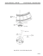
Refer to the Conduit Arrangement Wheelspace Thermocouples, draw-
ing in the Parts Lists and Drawings Volume of this Service Manual for
wheelspace thermocouple identification if needed.
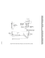
Operation 11 — How to Remove Mechanical Support Jacks from Underneath Turbine Casing
CAUTION
Mechanical support jacks are not to be removed until the
casing has been installed and bolted up.
1. Remove the mechanical support jacks and dial indicators from underneath the unit casing flanges.
2. Remove any shim packs if used, applicable to bases that have a transaxial “I” beam only.
3. Replace the base cutout floor plates and bolt in place.
4. Accumulate all jacks and dial indicators and return to storage.
Operation 12 — How to Take Final Compressor and Turbine Rotor Positioning Checks
Note:
All rotor positioning checks should be submitted to your General Elec-
tric Company Field Service Representative for evaluation. Both the ini-
tial and final readings should be submitted. All final readings must be
within tolerances as specified on the Clearance Diagram, in the Refer-
ence Drawing section of this Service Manual.
1. To take final rotor positioning checks, follow procedures outlined in Disassembly Operation 3
in this section.
2. Record all readings on Inspection Form PGS/GT-FF-6094 Rotor Positioning Checks.
Operation 13 — Perform Combustion Inspection Reassembly Operations 3 Through 14
Note:
Refer to the Combustion Inspection section in this Service Manual for
reassembly procedures for the following operations.
1. Install outer combustion casings and flow sleeves.
2. Install outer crossfire tubes, packing rings, sealing rings and split washers.
3. Install inner crossfire tubes and cap and liner assemblies.
4. Assemble primary flame detectors and spark plugs to outer combustion casings.
5. Install primary fuel nozzle/end cover assemblies.
6. Install secondary fuel nozzles.
7. Reconnect false start drain lines.
Summary of Contents for MS6001B
Page 2: ...Gas Turbine Inspection and Maintenance GEK 107048 I 2 THIS PAGE INTENTIONALLY LEFT BLANK ...
Page 4: ...Inspection and Maintenance Note THIS PAGE INTENTIONALLY LEFT BLANK ...
Page 13: ...INSERT TAB INTRODUCTION ...
Page 14: ......
Page 25: ...INSERT TAB STANDARD PRACTICES ...
Page 26: ......
Page 87: ...INSERT TAB AUXILIARY CONTROLS SYSTEMS MAINTENANCE ...
Page 88: ......
Page 133: ...INSERT TAB SCHEDULED TURBINE MAINTENACE ...
Page 134: ......
Page 157: ...INSERT TAB COMBUSTION INSPECTION ...
Page 158: ......
Page 239: ...INSERT TAB HOT GAS PATH INSPECTION ...
Page 240: ......
Page 313: ...INSERT TAB MAJOR INSPECTION ...
Page 314: ......
Page 316: ...Inspection and Maintenance GEK 107048 Major Inspection 2 THIS PAGE INTENTIONALLY LEFT BLANK ...
Page 363: ...INSERT TAB MAINTENANCE FORMS ...
Page 364: ......

