Scheduled Turbine Maintenance
Inspection and Maintenance — GEK 107048
STM-3
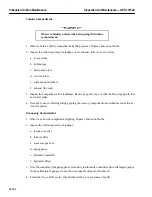
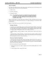
5. Note loose or vibrating piping conduit, or other fittings, and schedule repairs if necessary.
6. Check faces of clutch for cleanliness or possible damage. Clean or schedule maintenance as appro-
priate.
7. Inspect for evidence of overheating of accessory components (such as paint discoloration), and
schedule maintenance inspection or test of suspect components.
Off-Base Systems
1. Note loose or vibrating piping, conduit, or fittings. Schedule maintenance action if required.
2. Clean the floors of dirt, water, fuel, or lubricating oil spills. Dispose of rags and other debris.
General
1. Check door seals for deterioration. Schedule replacement as required.
2. Observe shutdown oil levels for the turbine, atomizing air compressor, atomizing air booster com-
pressor and turning gear. Note discrepancies, investigate cause, and refill all components to proper
oil levels as required.
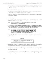
Data Recording
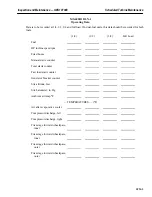
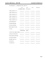
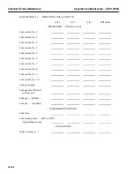
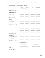
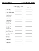
Operating data should be recorded to permit an evaluation of equipment performance and maintenance
requirements. Typical data includes load, exhaust temperature, vibration, fuel flow and pressure, exhaust
temperature control and variation, and startup time.
The vibration level of the unit should be observed and recorded. Minor changes in vibration level will
occur with changes in operating conditions. However, major changes in the vibration level or a continu-
ously increasing trend to increase warrants corrective action.
The fuel system should be observed for general fuel flow versus load relationship. Fuel pressures through
the system should be observed. Changes in fuel pressure may indicate that fuel nozzle passages are
plugged (dirty) or that fuel metering elements are damaged or out of calibration.
The variation in turbine exhaust temperature should be measured. An increase in temperature spread indi-
cates combustion system deterioration or fuel distribution problems. If this is not corrected, reduced life
of downstream parts can be expected.
One of the most important control functions to be observed is the exhaust temperature control system, and
its backup overtemperature trip circuitry. Routine verification of the operation and calibration of these
systems will minimize wear on the hot gas path parts.
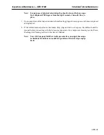
Startup time (when the gas turbine is new) is an excellent reference to which subsequent operating parame-
ters can be compared and evaluated. A curve of starting parameters of speed, fuel VCE signal, exhaust
temperature, and critical sequence benchmarks versus time from the initial start signal provide a good in-
dication of the accuracy of the control system, fuel system, fuel nozzles, ignition, and combustion system.
Deviations from normal conditions help pinpoint impending trouble, changes in calibration, or damaged
components.
Summary of Contents for MS6001B
Page 2: ...Gas Turbine Inspection and Maintenance GEK 107048 I 2 THIS PAGE INTENTIONALLY LEFT BLANK ...
Page 4: ...Inspection and Maintenance Note THIS PAGE INTENTIONALLY LEFT BLANK ...
Page 13: ...INSERT TAB INTRODUCTION ...
Page 14: ......
Page 25: ...INSERT TAB STANDARD PRACTICES ...
Page 26: ......
Page 87: ...INSERT TAB AUXILIARY CONTROLS SYSTEMS MAINTENANCE ...
Page 88: ......
Page 133: ...INSERT TAB SCHEDULED TURBINE MAINTENACE ...
Page 134: ......
Page 157: ...INSERT TAB COMBUSTION INSPECTION ...
Page 158: ......
Page 239: ...INSERT TAB HOT GAS PATH INSPECTION ...
Page 240: ......
Page 313: ...INSERT TAB MAJOR INSPECTION ...
Page 314: ......
Page 316: ...Inspection and Maintenance GEK 107048 Major Inspection 2 THIS PAGE INTENTIONALLY LEFT BLANK ...
Page 363: ...INSERT TAB MAINTENANCE FORMS ...
Page 364: ......

