


Inspection and Maintenance — GEK 107048
Hot Gas Path Inspection — Disassembly Procedures
HGP-D-2
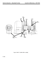
2. On side exhaust configurations remove any architectural lagging and support members which
may interfere with turbine casing removal.
Note:
Before the removable panel on the forward wall of the units exhaust
plenum can be removed, the upper section (right side looking with air
flow) of the 11th stage extraction piping and compressor bleed valve
(33CB-2) must be removed.
3. Disconnect the tubing runs attached to the head of the bleed valve and the tubing runs attached
to the extraction piping at both ends. Remove the “U” bracket that supports the actuating cylinder,
loosen the slip joint clamp and unbolt the extraction line from the compressor casing.
4. Rig to remove the piping, slip the piping out of the expansion joint and lift the piping clear of the
unit. Set the piping on suitable material to protect the valve and tubing runs. Cover all openings
on piping and compressor casing.
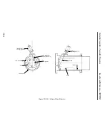
5. Remove the forward upper half segment clamp bars and the flex seal plates between the exhaust
hood frame and exhaust plenum.
6. Unbolt the forward exhaust plenum removable access panel. Rig to lift the panel.
Note:
The compressor bleed valve discharge pipe, insulating packs and the
compressor bleed valve diffuser box are part of this panel and should
not have to be removed.
7. Install a length of 4 in. pipe or timber and 10 ton mechanical jack across the horizontal opening
of the plenum and spread the plenum sufficiently enough to remove the access panel. Lift panel
clear of the unit.
8. Unbolt and remove the inlet plenum access door located in the lower right hand section of the
plenum, looking with air flow.
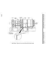
Operation 3 — How to Take Initial Compressor and Turbine Rotor Positioning Checks
Note:
Rotor positioning checks must be done with all casings bolted in place
and unit supported on its own supports.
CAUTION
Do not confuse clearanceometer holes and probe holes.
Clearanceometer holes are too small for a depth microme-
ter. Use probe holes for taking tip clearances on turbine
and compressor.
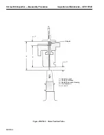
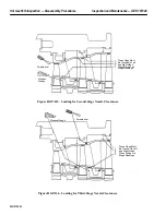
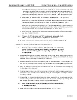
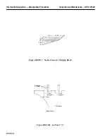
1. Using random first-stage compressor blades, take feeler clearance checks at six points: top cen-
terline, bottom centerline, and above and below the horizontal joint on each side. Record clear-
ances on PGS/GT-FF-6094 Inspection Form.
Summary of Contents for MS6001B
Page 2: ...Gas Turbine Inspection and Maintenance GEK 107048 I 2 THIS PAGE INTENTIONALLY LEFT BLANK ...
Page 4: ...Inspection and Maintenance Note THIS PAGE INTENTIONALLY LEFT BLANK ...
Page 13: ...INSERT TAB INTRODUCTION ...
Page 14: ......
Page 25: ...INSERT TAB STANDARD PRACTICES ...
Page 26: ......
Page 87: ...INSERT TAB AUXILIARY CONTROLS SYSTEMS MAINTENANCE ...
Page 88: ......
Page 133: ...INSERT TAB SCHEDULED TURBINE MAINTENACE ...
Page 134: ......
Page 157: ...INSERT TAB COMBUSTION INSPECTION ...
Page 158: ......
Page 239: ...INSERT TAB HOT GAS PATH INSPECTION ...
Page 240: ......
Page 313: ...INSERT TAB MAJOR INSPECTION ...
Page 314: ......
Page 316: ...Inspection and Maintenance GEK 107048 Major Inspection 2 THIS PAGE INTENTIONALLY LEFT BLANK ...
Page 363: ...INSERT TAB MAINTENANCE FORMS ...
Page 364: ......