Inspection and Maintenance Procedures
Inspection and Maintenance
IMP–10
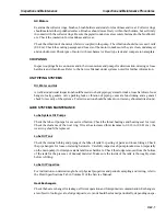
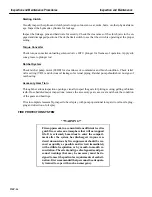
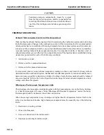
Use of a mercury manometer is not recommended. Mercury will react destructively with copper and
brass in system components under certain conditions, if it were accidentally injected into the cooling
water system.
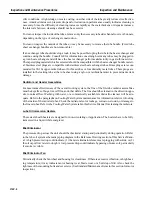
Flow Versus Pressure Drop
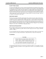
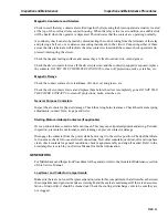
Water (or coolant) flow versus pressure drop curves may be prepared for any orifice* size by using the
equation:
Q
+
300KA
P
Ǹ
+
gpm
where the symbols are as follows:
B
+
Do (orifice)
Di
(pipe I.D.)
K
+
C
d
1
*
B
4
Ǹ
P
+
PSI (orifice)
A
+
AREA OF ORIFICE
+
(IN)
2
+
WATER DENSITY LB
ń
(FT)
3
C
d
+
ORIFICE DISCHARGE COEFFICIENT
The flow coefficient K for flange taps is determined experimentally; therefore, it may be extracted from
tables available in several references.*
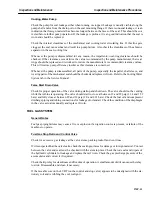
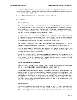
Water Tank
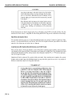
Examine the internal surface of the tank for cleanliness and the presence of algae or foreign matter. If
water leaks consistently from the tank fill opening with little change in ambient conditions, check the
pressure cap for the proper opening pressure setting. Also check for a missing cap gasket, poor gasket
surface, or damaged filler neck sealing surface. The pressure setting should be within
±
15% of the pres-
sure cap rating. The vacuum valve should open between zero psig (0 bars) and 1/2 psi (0.035 bars) vacu-
um. Check for leakage at the tank cover and gasket.
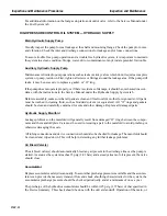
Cooling Water Fans
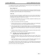
If the turbine is equipped with an off base cooling water module, annually check the cooling water
radiator fans, the fan housings and the motors for cleanliness, vibration, noise, blade damage, rust and
corrosion, and mounting bolt security. Make sure there are no obstructions in the inlet and outlet duct
work and that screens are clean. For detailed information on the inspection, maintenance disassembly
and reassembly of the fan, refer to the instructions under the Cooling Water System tab in the Service
Manual.
*ASME publication “Fluid Meters — Their Theory and Application” (Fifth Edition). Also, Crane Co., Technical Paper No. 410 “Flow of Fluids
Through Valves, Fittings and Pipe”.
Summary of Contents for MS6001B
Page 2: ...Gas Turbine Inspection and Maintenance GEK 107048 I 2 THIS PAGE INTENTIONALLY LEFT BLANK ...
Page 4: ...Inspection and Maintenance Note THIS PAGE INTENTIONALLY LEFT BLANK ...
Page 13: ...INSERT TAB INTRODUCTION ...
Page 14: ......
Page 25: ...INSERT TAB STANDARD PRACTICES ...
Page 26: ......
Page 87: ...INSERT TAB AUXILIARY CONTROLS SYSTEMS MAINTENANCE ...
Page 88: ......
Page 133: ...INSERT TAB SCHEDULED TURBINE MAINTENACE ...
Page 134: ......
Page 157: ...INSERT TAB COMBUSTION INSPECTION ...
Page 158: ......
Page 239: ...INSERT TAB HOT GAS PATH INSPECTION ...
Page 240: ......
Page 313: ...INSERT TAB MAJOR INSPECTION ...
Page 314: ......
Page 316: ...Inspection and Maintenance GEK 107048 Major Inspection 2 THIS PAGE INTENTIONALLY LEFT BLANK ...
Page 363: ...INSERT TAB MAINTENANCE FORMS ...
Page 364: ......

