Hot Gas Path Inspection — Reassembly Procedures
Inspection and Maintenance — GEK 107048
HGP-R-13
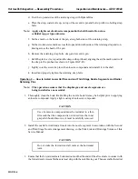
2. Record all final clearance readings on Inspection Form PGS/GT-FF-6105.
Operation 8 — How to Install Transition Pieces
Note:
Refer to the Combustion Inspection, Reassembly Operations 1 and 2 of
this Service Manual for transition piece installation procedure.
Operation 9 — How to Install Upper Half Turbine Casing and Upper Half First Stage
Nozzle Eccentric Pin
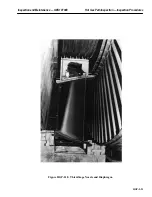
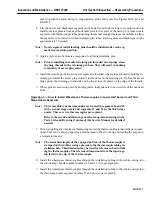
1. Attach and rig wire rope slings to the outer upper lugs of the spreader bar and to the overhead
crane. Pickup the spreader bar and position it over the turbine casing.
2. Using wire rope slings, rig the two aft lower lugs of the spreader bar to the aft lugs of the turbine
casing. Using chainfalls or comealongs and wire rope slings rig the forward lower set of lugs to
the forward lugs on the turbine casing. Position the spreader bar as close to the turbine casing as
a safe lifting angle will allow. Rigging should be such that when the wire rope slings are taut, the
bottom of the spreader bar should be fairly close to the highest section of the turbine casing.
Note:
The upper half turbine casing weight with the second and third stage
nozzle segments and shrouds is approximately 7300 pounds.
3. Flat file and wipe off the horizontal joints of the turbine casing lower half.
4. Apply Perfect Seal to the surface of the horizontal joint of the turbine case lower half and the verti-
cal joints of the compressor discharge casing and exhaust frame for a distance of one inch on both
sides of the four way joints.
CAUTION
Only a thin film of anti-seize compound is to be used or it
will interfere with pulling the joint together and act as a
gasket. Do not get anti-seize compound into the hot gas
path areas.
5. Apply a thin film of anti-seize compound to the horizontal joint of the turbine casing lower half
and to the vertical joints of the compressor discharge casing and exhaust frame.
Note:
Check the seals and seal strip fits for second and third stage nozzle seg-
ments. It may be necessary to grind them some to facilitate realignment
and reassembly of the upper half nozzles and turbine casing to the low-
er half turbine casing and nozzle segments.
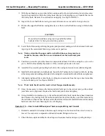
6. Lift the turbine casing and level it off. Flat file and wipe off the horizontal and vertical joints.
7. Lightly lubricate and install guide pins in the upper half casing horizontal joints body bound hole
locations.
8. Lift the turbine casing over the center of the unit and lower the casing until the aft end clears the
lifting beam and trolley hoist. Move the trolley hoist up against its forward stop.
Summary of Contents for MS6001B
Page 2: ...Gas Turbine Inspection and Maintenance GEK 107048 I 2 THIS PAGE INTENTIONALLY LEFT BLANK ...
Page 4: ...Inspection and Maintenance Note THIS PAGE INTENTIONALLY LEFT BLANK ...
Page 13: ...INSERT TAB INTRODUCTION ...
Page 14: ......
Page 25: ...INSERT TAB STANDARD PRACTICES ...
Page 26: ......
Page 87: ...INSERT TAB AUXILIARY CONTROLS SYSTEMS MAINTENANCE ...
Page 88: ......
Page 133: ...INSERT TAB SCHEDULED TURBINE MAINTENACE ...
Page 134: ......
Page 157: ...INSERT TAB COMBUSTION INSPECTION ...
Page 158: ......
Page 239: ...INSERT TAB HOT GAS PATH INSPECTION ...
Page 240: ......
Page 313: ...INSERT TAB MAJOR INSPECTION ...
Page 314: ......
Page 316: ...Inspection and Maintenance GEK 107048 Major Inspection 2 THIS PAGE INTENTIONALLY LEFT BLANK ...
Page 363: ...INSERT TAB MAINTENANCE FORMS ...
Page 364: ......

