Inspection and Maintenance — GEK 107048
Hot Gas Path Inspection — Disassembly Procedures
HGP-D-24
CAUTION
At all points where the segment and pulling cable come in
contact there should be ample padding to distribute the
load and protect the partition surfaces. Wood, rubber or
padded steel plates can be used.
Excessive shock and vibration should be avoided. Attach
cabling to the center nozzle partition if possible. A maxi-
mum force of 2,000 pounds should not be exceeded. The
wheelspace thermocouples must be removed prior to re-
moval of the nozzle segments. The “replaceable type”
thermocouples in the lower turbine casing are located in
segments number 10 and 15 in second stage nozzle, two
thermocouples per segment. The third stage nozzle ther-
mocouples, two per segment, are located in segments
number 11 and 14.
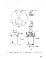
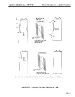
2. Tooling required for nozzle segment removal are: pulley assembly, one-ton “come-along”, and
0.375 in. wire rope or fiber sling. See Special Tools in the Standard Practices section of this Ser-
vice Manual.
Note:
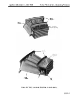
Pay particular attention to the nozzle and diaphragm forward, aft and
radial seals between each segment when rolling the nozzle segment out.
keep each set of seals with its respective segment. Place the removed
nozzle segments on a piece of plywood or equivalent in a protected area.
Cover the removed segments to protect them from the environment.
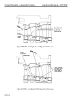
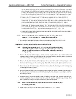
3. Attach cable to nozzle segment 16 and remove the segment using a one-ton “come-along” at-
tached to the overhead crane.
4. Attach cable to nozzle segment 15 and remove.
5. Install pulley assembly in retaining pin hole 16. Pass cable through pulley and attach to nozzle
segment 14. Pull nozzle segment to position vacated by nozzle segment 15. Remove pulley as-
sembly and remove nozzle segment 14 as above.
6. Install pulley assembly in retaining pin hole 15. Pass cable through pulley and attach to nozzle
segment 13. Pull nozzle segment 13 to position vacated by nozzle segment 14. Move pulley to
pin hole 16 and remove nozzle segment 13 as above.
7. Install pulley assembly in retaining pin hole 14. Pass cable through pulley and attach to nozzle
segment 12. Pull nozzle segment to position vacated by nozzle segment 13. Move pulley assem-
bly to pin hole 15 and then to pin hole 16 and remove nozzle segment 12 as above.
8. Move to other side of unit and remove segments 9, 10 and 11 in same manner as described above.
Summary of Contents for MS6001B
Page 2: ...Gas Turbine Inspection and Maintenance GEK 107048 I 2 THIS PAGE INTENTIONALLY LEFT BLANK ...
Page 4: ...Inspection and Maintenance Note THIS PAGE INTENTIONALLY LEFT BLANK ...
Page 13: ...INSERT TAB INTRODUCTION ...
Page 14: ......
Page 25: ...INSERT TAB STANDARD PRACTICES ...
Page 26: ......
Page 87: ...INSERT TAB AUXILIARY CONTROLS SYSTEMS MAINTENANCE ...
Page 88: ......
Page 133: ...INSERT TAB SCHEDULED TURBINE MAINTENACE ...
Page 134: ......
Page 157: ...INSERT TAB COMBUSTION INSPECTION ...
Page 158: ......
Page 239: ...INSERT TAB HOT GAS PATH INSPECTION ...
Page 240: ......
Page 313: ...INSERT TAB MAJOR INSPECTION ...
Page 314: ......
Page 316: ...Inspection and Maintenance GEK 107048 Major Inspection 2 THIS PAGE INTENTIONALLY LEFT BLANK ...
Page 363: ...INSERT TAB MAINTENANCE FORMS ...
Page 364: ......


