Inspection and Maintenance — GEK 107048
Hot Gas Path Inspection — Reassembly Procedures
HGP-R-6
d. Coat the top and sides of the retaining strap with Dykem Blue.
e. Place the strap, coated side up, on top of the eccentric pin and bolt up with two bolting strap
bolts.
Note:
Apply a light coat of anti-seize compound to the bolt threads. Do not use
colloidal copper type anti-seize.
f. Scribe a mark on the heads of the pin, along both sides of the retaining strap.
g. Scribe two transverse marks across the tops and down the sides of the retaining strap and con-
tinuing across the head of the pin.
h. Remove the retaining strap bolts, strap, and eccentric pin.
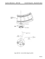
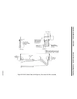
i. Hold the pin in a vise, reposition the strap on the pin head, aligning the scribe marks, and weld
the strap to the pin head as shown in Figure HGP-R.1.
j. Lightly coat the eccentric pin with anti-seize compound and reinstall it in the shell.
k. Install and properly tighten the retaining strap bolts.
Operation 2 — How to Install Lower Half Second and Third Stage Nozzle Segments and Radial
Retaining Pins
Note:
This operation assumes that the diaphragm and nozzle segments are
being installed as one assembly.
1. Thoroughly clean the hook fits. Buffing the nozzle hook fits may be helpful prior to applying
anti-seize compound. Apply a light coating of anti-seize compound.
CAUTION
Use of anti-seize compound must be restricted to a thin
film such that the compound is not forced into the inner
gas path. Should this occur, it must be carefully removed.
2. Install the nozzle forward and aft seals into the nozzle segment in accordance with the Second
and Third Stage Nozzle Arrangement drawing, in the Parts Lists and Drawings Volume of this
Service Manual.
CAUTION
Do not stake the forward and aft seals at the horizontal
joint.
3. Ensure that the forward seals are bottomed out and that the ends of the aft seals are in contact with
the forward seals. Assemble the axial seal strip with the notch facing out. Then assemble the radial
Summary of Contents for MS6001B
Page 2: ...Gas Turbine Inspection and Maintenance GEK 107048 I 2 THIS PAGE INTENTIONALLY LEFT BLANK ...
Page 4: ...Inspection and Maintenance Note THIS PAGE INTENTIONALLY LEFT BLANK ...
Page 13: ...INSERT TAB INTRODUCTION ...
Page 14: ......
Page 25: ...INSERT TAB STANDARD PRACTICES ...
Page 26: ......
Page 87: ...INSERT TAB AUXILIARY CONTROLS SYSTEMS MAINTENANCE ...
Page 88: ......
Page 133: ...INSERT TAB SCHEDULED TURBINE MAINTENACE ...
Page 134: ......
Page 157: ...INSERT TAB COMBUSTION INSPECTION ...
Page 158: ......
Page 239: ...INSERT TAB HOT GAS PATH INSPECTION ...
Page 240: ......
Page 313: ...INSERT TAB MAJOR INSPECTION ...
Page 314: ......
Page 316: ...Inspection and Maintenance GEK 107048 Major Inspection 2 THIS PAGE INTENTIONALLY LEFT BLANK ...
Page 363: ...INSERT TAB MAINTENANCE FORMS ...
Page 364: ......


