Standard Practices
Inspection and Maintenance
SP–2
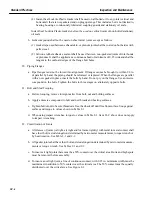
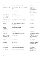
5. Clean all removed parts, and fasteners and store in separate containers, tagged to simplify reassemb-
ly. (See Gas Turbine Cleaning in this section for cleaning methods.)
6. Use penetrating oil prior to bolt removal. (Refer to recommended solvents, sealers, cleaners, etc.
in this section for listing of acceptable penetrating oils.)
7. Protect all casing flanges from rust and mechanical damage after removal. Grease, layout dye or
commercial rust inhibitors will retard flange rusting and plywood, masonite, or equal will prevent
mechanical damage.
8. Deburr mating surfaces and eliminate flange face high spots before assembling any casings. Carbo-
rundum stones and flat mill files are effective for these tasks.
9. Cover all open pipe and tubing. Do not stuff rags in pipes. Sheet metal or plywood are effective cov-
ers for large pipes and duct tape will protect tubing.
10. Never use pipe wrenches or pliers on tube fittings.
11. Do Not Reuse Gaskets — unless specifically instructed to do so in the procedures.
12. Do not reuse lockplates internal to the unit or those noted with a double asterisk (**). (Refer to the
Maintenance Parts Recommendations in this section.)
13. Match mark piping, fuel nozzles, couplings and casings to assist in proper orientation during reas-
sembly.
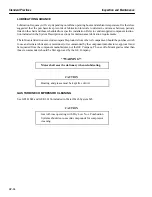
14. Do not mark on any combustion system or turbine components with any compounds containing
lead. Carters Marks-A-Lot, black or blue, Dixon Company black or blue, Everhard Faber #7500 Wa-
ter Color, black, Dykem Company dark blue, Dykem DSL, light blue, Dykem DMP, high spot blue,
Dykem 107, Joseph Dixon lead free yellow lumber crayons, Wallace Pencil Company #800 black
marker, Machine Manufacturing Company Marco S-1141 black and Marco S-1141 white are rec-
ommended and approved markers. Nickel base alloys are subject to attack when heated in the pres-
ence of sulfur, lead and other metals. These materials can cause embrittlement and cracking at ele-
vated temperatures. Some common sources of these compounds are paint, markers and machining
oil. Use of tags wired to the parts (avoid aluminum or other low melting point alloys), and markers
certified free of injurious materials can eliminate this source of contamination.
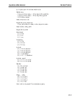
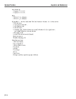
15. Observe the following general precautions when the unit is undergoing major inspection, mainte-
nance checks and taking clearance readings.
a. Axial readings must be taken with the rotor positioned in contact with the active face of the
thrust bearing. Any pressure applied in moving the rotor should be released prior to taking rotor
position or clearance measurements.
b. Parallel bars and feeler stock, when used with proper attention to detail, provide good measure-
ments. In order to obtain proper measurement accuracy, the total thickness of the parallel bar
and feeler stock must be measured with a micrometer.
c. Snap gauges may be used to obtain measurements when proper attention is applied to the gauge
orientation. Snap gauges used on bevel surfaces will result in inaccurate readings.
Summary of Contents for MS6001B
Page 2: ...Gas Turbine Inspection and Maintenance GEK 107048 I 2 THIS PAGE INTENTIONALLY LEFT BLANK ...
Page 4: ...Inspection and Maintenance Note THIS PAGE INTENTIONALLY LEFT BLANK ...
Page 13: ...INSERT TAB INTRODUCTION ...
Page 14: ......
Page 25: ...INSERT TAB STANDARD PRACTICES ...
Page 26: ......
Page 87: ...INSERT TAB AUXILIARY CONTROLS SYSTEMS MAINTENANCE ...
Page 88: ......
Page 133: ...INSERT TAB SCHEDULED TURBINE MAINTENACE ...
Page 134: ......
Page 157: ...INSERT TAB COMBUSTION INSPECTION ...
Page 158: ......
Page 239: ...INSERT TAB HOT GAS PATH INSPECTION ...
Page 240: ......
Page 313: ...INSERT TAB MAJOR INSPECTION ...
Page 314: ......
Page 316: ...Inspection and Maintenance GEK 107048 Major Inspection 2 THIS PAGE INTENTIONALLY LEFT BLANK ...
Page 363: ...INSERT TAB MAINTENANCE FORMS ...
Page 364: ......


