Inspection and Maintenance
Inspection and Maintenance Procedures
IMP–23
Magnetic Contactors and Starters
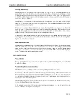
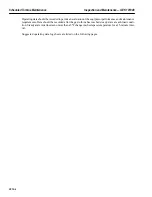
Check to see if the relay contacts are welded together by depressing the brown operator (actuator), located
at the top of the overload relay contact housing. When the relay is in a reset condition, an audible click
will be heard when the operator is depressed. This indicates that the contacts are operating normally.
A continuity check can also be made by disconnecting the control wiring from the terminals of the relay
and placing a bell set, or a resistance measuring instrument, in the circuit. Connecting either of these
across the relay terminals, will indicate the relay contact is closed until the contact-check operator is de-
pressed; interrupting the circuit.
Check the magnet mating surfaces and assure they are free from dust, dirt, oil and grease.
Check the silver contacts for wear. If the silver tip is worn, and the contact tip support is exposed, replace
the contacts. DO NOT FILE THE SILVER CONTACTS to clean off projections, nicks, scratches, etc.
Magnetic Relays
Check the contact surfaces for cleanliness, dirt, dust, oil and grease, etc.
Check the silver contacts for wear and replace them before the silver is completely gone. DO NOT FILE
THE SILVER CONTACTS to clean off projections, nicks, scratches, etc.
General Purpose Contactors
Inspect the arc chute for physical damage. Check the arcing horn clearances. Check the armature spring
adjustments, contact force, tie gaps and wires.
Starting Motor Limitamp Contactor (if applicable)
Over a period of time contactor bolts can loosen. This may cause tip misalignment and arcing. Periodic
inspection, preventative maintenance and cleaning can prevent contactor damage.
Disengage the contactor from the power stabs by moving it to the service position. Check all hardware
for looseness, check for loose electrical connections, blow off accumulations of dust, dirt and wipe base
clean, check contacts for general conditions, check magnet assembly and align if needed. Refer to the
Limitamp Devices tab in your Service Manual for further information.
GENERATORS
For Maintenance and Inspection Procedures for the generator refer to the Generator Maintenance section
of this Service Manual.
Load Gear and Collector Compartments
Make sure there are no loose fiberglass expansion joints in this compartment, that all interfaces between
the compartment and generator ends are watertight, and the seals are not damaged. If there is an accumu-
lation of dust or dirt, it should be cleaned out. Check the cooling air discharge vents to be sure they are
not clogged.
Summary of Contents for MS6001B
Page 2: ...Gas Turbine Inspection and Maintenance GEK 107048 I 2 THIS PAGE INTENTIONALLY LEFT BLANK ...
Page 4: ...Inspection and Maintenance Note THIS PAGE INTENTIONALLY LEFT BLANK ...
Page 13: ...INSERT TAB INTRODUCTION ...
Page 14: ......
Page 25: ...INSERT TAB STANDARD PRACTICES ...
Page 26: ......
Page 87: ...INSERT TAB AUXILIARY CONTROLS SYSTEMS MAINTENANCE ...
Page 88: ......
Page 133: ...INSERT TAB SCHEDULED TURBINE MAINTENACE ...
Page 134: ......
Page 157: ...INSERT TAB COMBUSTION INSPECTION ...
Page 158: ......
Page 239: ...INSERT TAB HOT GAS PATH INSPECTION ...
Page 240: ......
Page 313: ...INSERT TAB MAJOR INSPECTION ...
Page 314: ......
Page 316: ...Inspection and Maintenance GEK 107048 Major Inspection 2 THIS PAGE INTENTIONALLY LEFT BLANK ...
Page 363: ...INSERT TAB MAINTENANCE FORMS ...
Page 364: ......


