Inspection and Maintenance — GEK 107048
Combustion Inspection — Reassembly Procedures
CI-R-20
Note:
Use of grease or some other adhesive will help to retain the gasket in the
groove.
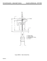
2. Carefully insert secondary nozzle through the center hole of the primary fuel nozzle/end cover
assembly. The secondary fuel nozzle tip will start to engage or set in place when the secondary
nozzle assembly flange is approximately 0.5 inch from the primary fuel nozzle flange. Before this
engagement point, make sure that the alignment is correct.
CAUTION
If more than hand force is required to bring the secondary
nozzle body flange to the cover gasket, it is misaligned!
Stop and realign to prevent damage. Hold nozzle body in
place until one bolt is fully installed.
3. Install the remaining mounting bolts and progressively torque the bolts in a criss-cross sequence.
4. Proceed to install the rest of the secondary nozzles.
Operation 9 — How to Reconnect the False Start Drain Lines
1. Reconnect the false start drain lines to combustion casing covers 3, 4, 5, 6 and 7.
2. Tighten the swagelok nut until the collar cannot be rotated by hand.
Operation 10 — How to Install the 11th Stage Cooling and Sealing Air Lines
1. On reassembly of piping, use new gaskets on all gasketed joints.
2. Assemble 11th stage piping removed being careful to replace orifices in their proper location
from where they were removed at disassembly.
Note:
In the event that the location identification of the orifices become lost,
refer to the Reference Drawings volume of this Service Manual. The
cooling and sealing air piping diagram in this section will give the prop-
er location and orifice sizes required.
Operation 11 — How to Install the Primary, Secondary and Transfer Gas Fuel Lines
1. Using new gaskets, connect the flexible gas fuel lines between the fuel nozzle flange and the man-
ifold flange.
2. The order of installation of these flexible gas lines is generally from the bottom of the turbine to
the top, and from the radial inside to the radial outside.
3. Tighten bolts in a criss–cross pattern to give uniform gasket compression.
Summary of Contents for MS6001B
Page 2: ...Gas Turbine Inspection and Maintenance GEK 107048 I 2 THIS PAGE INTENTIONALLY LEFT BLANK ...
Page 4: ...Inspection and Maintenance Note THIS PAGE INTENTIONALLY LEFT BLANK ...
Page 13: ...INSERT TAB INTRODUCTION ...
Page 14: ......
Page 25: ...INSERT TAB STANDARD PRACTICES ...
Page 26: ......
Page 87: ...INSERT TAB AUXILIARY CONTROLS SYSTEMS MAINTENANCE ...
Page 88: ......
Page 133: ...INSERT TAB SCHEDULED TURBINE MAINTENACE ...
Page 134: ......
Page 157: ...INSERT TAB COMBUSTION INSPECTION ...
Page 158: ......
Page 239: ...INSERT TAB HOT GAS PATH INSPECTION ...
Page 240: ......
Page 313: ...INSERT TAB MAJOR INSPECTION ...
Page 314: ......
Page 316: ...Inspection and Maintenance GEK 107048 Major Inspection 2 THIS PAGE INTENTIONALLY LEFT BLANK ...
Page 363: ...INSERT TAB MAINTENANCE FORMS ...
Page 364: ......

