Inspection and Maintenance — GEK 107048
Combustion Inspection — Inspection Procedures
CI-I-10
Note:
At this time, after the transition piece has been torqued and before the
gas tip assembly is assembled, the oil gasket leak check described in
Fuel Nozzle Testing can be done. Instructions for such a leak test can
be obtained from your General Electric Field Service Representative.
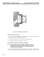
11. Wipe anti–seize compound lightly on the threads of the gas tip and on the corresponding threads
on the fuel nozzle body. Then slip a lock plate on the body.
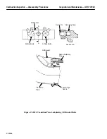
12. At this time, check the piston ring seals on the transition piece to be sure that they are free to rotate
in their slot.
13. Thread the outer tip onto the fuel nozzle, torque to the value shown on the secondary fuel nozzle
assembly drawing, and lock the lock plate with the special tool.
Operation 5 — How to Test Secondary Fuel Nozzles
Fuel Nozzle Gas Passage Effective Area Check
1. Both the secondary gas fuel passage and the transfer gas fuel passage must be flow checked in ac-
cordance with the values defined on the Secondary Fuel Nozzle Assembly drawing in the Parts
List and Drawings Volume of the Service Manual.
Operation 6 — How to Inspect Combustion Liners
Note:
Combustion liners will not be dealt with by any specific drawing num-
ber. Repair welding techniques will not be described except to note that
GTAW (Gas Tungsten Arc Welding) is the only weld repair procedure
allowed on MS-6001 combustion liners. It is generally recommended
that combustion liners requiring repairs, replacement of caps, liner
sleeves, and spring seals be sent to a qualified General Electric Compa-
ny Gas Turbine repair facility, and not repaired in the field. Coated
welding rod should not be used. Deterioration less than maximum al-
lowable limits indicates that reuse may be permissible provided consid-
eration has been given to past operating hours and firing conditions in
relation to the future operations expected.
Inspect Slot Cooled Liners
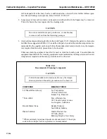
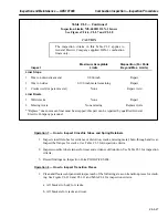
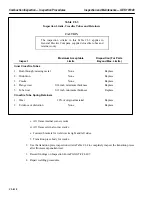
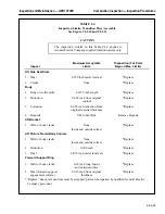
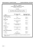
1. Table CI-2 is a guide which will aid in decision making on reuse, repair or discarding of slot cooled
combustion liners. Record findings in Inspection Form PGS/GT–FF–WS01 and PGS/GT–
FF–6406.
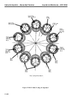
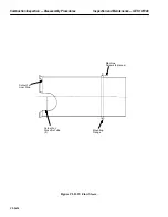
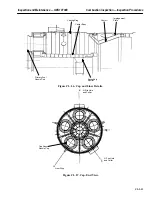
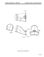
2. Figures CI-I.6, CI-I.7 and CI-I.8 should be used to identify areas of the slot cooled combustion
liner called for in Table CI-2.
3. Weld cracks shall be detected using fluorescent penetrant. Zyglo ZL2, ZL22 and ZL54 are accept-
able.
4. Cracks emanating from cooling holes or combustion holes should be detected using a bright light
and ten (10) power glass. The use of penetrants over the liner surface is discouraged except where
confirmation is required.
Summary of Contents for MS6001B
Page 2: ...Gas Turbine Inspection and Maintenance GEK 107048 I 2 THIS PAGE INTENTIONALLY LEFT BLANK ...
Page 4: ...Inspection and Maintenance Note THIS PAGE INTENTIONALLY LEFT BLANK ...
Page 13: ...INSERT TAB INTRODUCTION ...
Page 14: ......
Page 25: ...INSERT TAB STANDARD PRACTICES ...
Page 26: ......
Page 87: ...INSERT TAB AUXILIARY CONTROLS SYSTEMS MAINTENANCE ...
Page 88: ......
Page 133: ...INSERT TAB SCHEDULED TURBINE MAINTENACE ...
Page 134: ......
Page 157: ...INSERT TAB COMBUSTION INSPECTION ...
Page 158: ......
Page 239: ...INSERT TAB HOT GAS PATH INSPECTION ...
Page 240: ......
Page 313: ...INSERT TAB MAJOR INSPECTION ...
Page 314: ......
Page 316: ...Inspection and Maintenance GEK 107048 Major Inspection 2 THIS PAGE INTENTIONALLY LEFT BLANK ...
Page 363: ...INSERT TAB MAINTENANCE FORMS ...
Page 364: ......

