


Inspection and Maintenance — GEK 107048
Hot Gas Path Inspection — Reassembly Procedures
HGP-R-18
8. Install 11th stage cooling and sealing air lines.
Note:
Install all the 11th stage cooling and sealing air piping except the upper
right side section with the compressor bleed valve (33CB-2). This sec-
tion will be installed after the exhaust plenum access upper panel is re-
installed.
9. Install primary, secondary and transfer gas fuel lines.
10. Install turbine casing blank cover on hand holes port or the air extraction manifold.
11. Install secondary flame detectors.
12. Reconnect the ignitors.
Operation 14 — How to Reassemble Exhaust and Inlet Duct Access Panels
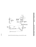
1. On a straight up exhaust configuration spread the exhaust plenum frame using a length of 4 in.
pipe or timber and a 10 ton mechanical jack sufficiently to allow clearance to install the access
panel.
2. Assemble new gasket, lift and position the panel into the plenum opening. Coat bolting with Fel
Pro C-102 anti-seize compound, install bolts but do not tighten.
3. Assemble new gasket to the exhaust duct transition piece forward panel. Lift and guide the panel
into position.
Note:
Comealongs will be required to help guide and position the panel into
location underneath the overhang of the duct transition piece.
4. Coat bolts with Fel Pro C-102 anti-seize compound. Install bolts and tighten. Remove the rigging.
5. Tighten the bolts on the exhaust plenum panel.
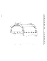
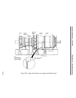
6. Reassemble the exhaust plenum forward flex seals gaskets and clamp bars between the exhaust
hood frame and plenum. See Figure HGP-R.8.
7. Reinstall the 11th stage extraction piping and compressor bleed valve to the exhaust plenum pan-
el. Reconnect all tubing runs and piping runs to the 11th stage piping and bleed valve.
8. Inspect the inlet plenum for cleanliness and or foreign objects. Install new gasket on the inlet ple-
num access panel located in the lower right hand section of the plenum, looking with air flow.
Coat bolts with anti-seize compound, install access panel and bolt in place.
Operation 15 — How to Assemble Turbine Compartment Roof, Side Panels and Doors
1. Reassemble lagging side panel vertical beams if they were removed at disassembly.
2. Attach four eyebolts to threaded receptacles on the roof. Rig the roof (include chainfall in rigging)
for lifting.
3. Apply new gasketing or caulking to roof section.
Summary of Contents for MS6001B
Page 2: ...Gas Turbine Inspection and Maintenance GEK 107048 I 2 THIS PAGE INTENTIONALLY LEFT BLANK ...
Page 4: ...Inspection and Maintenance Note THIS PAGE INTENTIONALLY LEFT BLANK ...
Page 13: ...INSERT TAB INTRODUCTION ...
Page 14: ......
Page 25: ...INSERT TAB STANDARD PRACTICES ...
Page 26: ......
Page 87: ...INSERT TAB AUXILIARY CONTROLS SYSTEMS MAINTENANCE ...
Page 88: ......
Page 133: ...INSERT TAB SCHEDULED TURBINE MAINTENACE ...
Page 134: ......
Page 157: ...INSERT TAB COMBUSTION INSPECTION ...
Page 158: ......
Page 239: ...INSERT TAB HOT GAS PATH INSPECTION ...
Page 240: ......
Page 313: ...INSERT TAB MAJOR INSPECTION ...
Page 314: ......
Page 316: ...Inspection and Maintenance GEK 107048 Major Inspection 2 THIS PAGE INTENTIONALLY LEFT BLANK ...
Page 363: ...INSERT TAB MAINTENANCE FORMS ...
Page 364: ......