


Inspection and Maintenance — GEK 107048
Major Inspection — Disassembly Procedures
MI-D-22
ing. Later vintage units the upper half bearing liner is bolted to the low-
er half bearing liner.
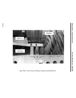
1. Disconnect and tag any instrumentation on the upper half bearing housing.
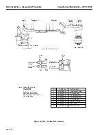
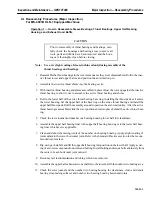
2. Loosen and remove the horizontal joint bolting on the number one bearing housing. See Figure
MI-D.10.
3. Install jacking bolts and jack the housing apart 0.100 in. or less to separate the horizontal joint.
4. Rig to lift the housing, using a chainfall, and lift the housing clear of the unit. Set the housing on
suitable blocking or plywood to protect from damage.
5. Unbolt and remove the upper half bearing liner from the lower half liner (if applicable).
6. Cover the open bearing housing to protect the rotor bearing journal and to keep the housing clean.
7. Identify wrap and/or cover the removed parts for protection.
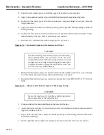
Number One Bearing Housing Thrust Bearings
1. Remove the active tilted pad thrust bearing from the bearing housing by carefully sliding out the
top three pads, rotating the cage to the split line, and lifting off the top of the cage.
2. Roll out the lower half cage and remove each pad as they become accessible.
3. Identify and tag the parts removed for reassembly.
4. Wrap the thrust bearing with protective wrap to prevent damage to parts.
5. Remove the upper and lower half tapered land inactive thrust bearing.
6. Identify and tag the parts removed for reassembly.
7. Wrap the thrust bearing with protective wrap to prevent damage to parts.
8. Cover the open lower half bearing housing to protect the bearing journal and keep the housing
clean.
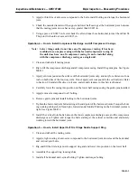
Number Two Bearing
Note:
The number two bearing is accessible for disassembly and reassembly
during major inspection since the exhaust frame is disassembled, how-
ever special fixturing (tooling) is provided to disassemble and reas-
semble the number two bearing with the exhaust frame in place.
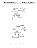
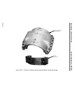
1. Loosen and remove the horizontal bolts from the bearing housing. See Figure MI-D.11 and
MI-D.12.
2. Using jack bolts, jack the housing apart to separate the horizontal joint.
3. Rig to lift the housing, using a chain fall, and lift the housing clear of the unit.
Summary of Contents for MS6001B
Page 2: ...Gas Turbine Inspection and Maintenance GEK 107048 I 2 THIS PAGE INTENTIONALLY LEFT BLANK ...
Page 4: ...Inspection and Maintenance Note THIS PAGE INTENTIONALLY LEFT BLANK ...
Page 13: ...INSERT TAB INTRODUCTION ...
Page 14: ......
Page 25: ...INSERT TAB STANDARD PRACTICES ...
Page 26: ......
Page 87: ...INSERT TAB AUXILIARY CONTROLS SYSTEMS MAINTENANCE ...
Page 88: ......
Page 133: ...INSERT TAB SCHEDULED TURBINE MAINTENACE ...
Page 134: ......
Page 157: ...INSERT TAB COMBUSTION INSPECTION ...
Page 158: ......
Page 239: ...INSERT TAB HOT GAS PATH INSPECTION ...
Page 240: ......
Page 313: ...INSERT TAB MAJOR INSPECTION ...
Page 314: ......
Page 316: ...Inspection and Maintenance GEK 107048 Major Inspection 2 THIS PAGE INTENTIONALLY LEFT BLANK ...
Page 363: ...INSERT TAB MAINTENANCE FORMS ...
Page 364: ......