Major Inspection — Disassembly Procedures
Inspection and Maintenance — GEK 107048
MI-D-9
6. Remove outer horizontal joint bolting left and right sides.
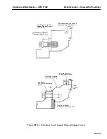
7. Grind off the welds from the bolt heads on the outer diffuser to inner diffuser strut ends (7 total)
on top half only and remove the bolts.
8. Remove the inner tunnel vertical joint top half bolts between the exhaust frame and exhaust diffus-
er.
9. Remove the inner tunnel horizontal joint bolts left and right sides.
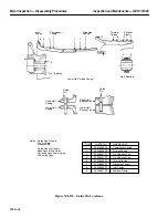
10. Move the trolley hoist over the center of gravity approximately 21 in. from the forward flange of
the exhaust frame. Lower the spreader bar until it is about 8–10 in. from the top of the exhaust
frame.
11. Rig by attaching one end of the wire rope sling to one of the lower lugs on the spreader bar. Feed
the other end through the lifting lugs on the exhaust frame and attach to the lug on the other side
of the spreader bar. Repeat for the other side.
Note:
The upper half exhaust frame assembly weighs approximately 4400
pounds.
12. Install the jacking bolts and jack the exhaust frame apart. Using the trolley hoist, gradually lift the
exhaust frame assembly to the maximum height allowed by the hoist.
13. Move the trolley hoist out of the exhaust duct transition piece to the trolley hoist stop. Using an
overhead crane, rig to the outer upper lugs of the spreader bar and transfer the load to the overhead
crane. Lift the exhaust frame clear of the unit and set on suitable cribbing.
Operation 9 — How to Remove Forward Compressor Casing
Note:
Later vintage units have a combined (one piece) forward and aft com-
pressor casing. Earlier units have a separate forward and aft compres-
sor casing. The following operation pertains to the combined case or the
forward case only, which ever is applicable. The aft compressor casing,
if applicable, will be removed with the compressor discharge casing as
a single unit when removed.
1. Remove the upper half bolting between the forward compressor and/or compressor casing, inlet
and aft compressor and/or compressor discharge casing vertical flanges. Pull the two upper verti-
cal joint dowels and tag for location.
2. Remove the horizontal flange bolting.
3. Remove the horizontal flange body bound bolts.
Note:
When removing the horizontal joint body bound bolts, they should be
driven upwards.
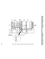
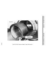
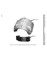
4. Utilizing the jack bolts and guide pins provided, separate the casing at the horizontal joint, rig and
lift the casing clear and set on suitable blocking. See Figure MI-D.2.
Summary of Contents for MS6001B
Page 2: ...Gas Turbine Inspection and Maintenance GEK 107048 I 2 THIS PAGE INTENTIONALLY LEFT BLANK ...
Page 4: ...Inspection and Maintenance Note THIS PAGE INTENTIONALLY LEFT BLANK ...
Page 13: ...INSERT TAB INTRODUCTION ...
Page 14: ......
Page 25: ...INSERT TAB STANDARD PRACTICES ...
Page 26: ......
Page 87: ...INSERT TAB AUXILIARY CONTROLS SYSTEMS MAINTENANCE ...
Page 88: ......
Page 133: ...INSERT TAB SCHEDULED TURBINE MAINTENACE ...
Page 134: ......
Page 157: ...INSERT TAB COMBUSTION INSPECTION ...
Page 158: ......
Page 239: ...INSERT TAB HOT GAS PATH INSPECTION ...
Page 240: ......
Page 313: ...INSERT TAB MAJOR INSPECTION ...
Page 314: ......
Page 316: ...Inspection and Maintenance GEK 107048 Major Inspection 2 THIS PAGE INTENTIONALLY LEFT BLANK ...
Page 363: ...INSERT TAB MAINTENANCE FORMS ...
Page 364: ......

