Hot Gas Path Inspection — Disassembly Procedures
Inspection and Maintenance — GEK 107048
HGP-D-15
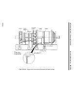
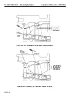
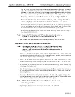
Assure that the third stage nozzle aft outer sidewall hooks are seated downstream in the third
stage shroud and the third stage shrouds are seated downstream against the turbine casing. As-
sure that the diaphragm forward male hook is seated downstream against the nozzle female
hook. This is indicated on Figure HGP-D.6, with the notation “These gaps must be closed.”
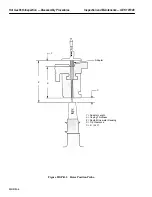
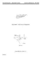
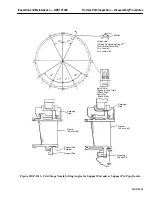
b. Measure the “B” dimension and “B” dimension complement. See Figure HGP-D.10.
Measure the “B” dimension, between the forward flat side, not the pointed portion of the sec-
ond long diaphragm seal tooth and the aft side of the second land of the 2–3 spacer.
Measure the “B” dimension complement, “B
C
,” between the aft flat side, not the pointed por-
tion, of each diaphragm seal tooth and the forward side of each spacer land. Proceed with the
forward tooth first for “B
C1
,” and proceed downstream for “B
C2
,” “B
C3
,” etc.
c. Measure all other radial and axial clearances around the third stage nozzle. Record on Inspec-
tion Form PGS/GT-FF-6105.
Note:
Measure the “B” dimension and “B7” complements using similar tech-
niques to “A” set point and “A” complement measurements.
5. Take all other accessible clearances. Record on Inspection Form PGS/GT-FF-6105.
Operation 9 — How to Unbolt and Remove Transition Pieces
Note:
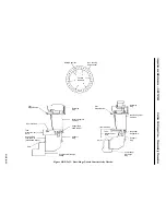
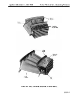
Transition pieces numbers 10, 1, 2, 3, 7, 8 and 9 can be removed radially
outward through the turbine casing opening. Transition pieces 4, 5 and
6 must be removed through the corresponding compressor discharge
casing opening.
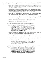
1. Remove the shoulder bolt, lockplate, and aft side seal stop from between 1 and 10 and 10 and 9
transition pieces. Remove the transition piece aft side seals radially outward. Identify the aft side
seals and seal stop according to transition piece location.
2. Remove the shoulder bolt(s) and lockplate(s) that secures the number 10 transition piece aft
bracket to the first stage nozzle retaining ring. Discard the bolt(s) and lockplate(s). Do not reuse.
3. Move the number 10 transition piece forward and away from the first stage nozzle retaining ring
to disengage the floating seals.
4. Slide the transition piece out of the forward support clamp (bullhorn) retaining slots and remove
the transition piece radially outward. Identify and tag the transition piece according to combus-
tion casing location.
5. Disassemble the forward mounting bracket lockplates, shoulder bolts, support clamp and for-
ward mounting block and or shims from the number 10 position. Identify support clamp block
and or shims according to location. Discard the bolts and lockplates.
Note:
Refer to the Standard Practices section in this Service Manual for prop-
er marking procedure.
6. Repeat steps 1 through 5 for transition pieces numbers 1, 2, 3, 7, 8 and 9.
Summary of Contents for MS6001B
Page 2: ...Gas Turbine Inspection and Maintenance GEK 107048 I 2 THIS PAGE INTENTIONALLY LEFT BLANK ...
Page 4: ...Inspection and Maintenance Note THIS PAGE INTENTIONALLY LEFT BLANK ...
Page 13: ...INSERT TAB INTRODUCTION ...
Page 14: ......
Page 25: ...INSERT TAB STANDARD PRACTICES ...
Page 26: ......
Page 87: ...INSERT TAB AUXILIARY CONTROLS SYSTEMS MAINTENANCE ...
Page 88: ......
Page 133: ...INSERT TAB SCHEDULED TURBINE MAINTENACE ...
Page 134: ......
Page 157: ...INSERT TAB COMBUSTION INSPECTION ...
Page 158: ......
Page 239: ...INSERT TAB HOT GAS PATH INSPECTION ...
Page 240: ......
Page 313: ...INSERT TAB MAJOR INSPECTION ...
Page 314: ......
Page 316: ...Inspection and Maintenance GEK 107048 Major Inspection 2 THIS PAGE INTENTIONALLY LEFT BLANK ...
Page 363: ...INSERT TAB MAINTENANCE FORMS ...
Page 364: ......


