Inspection and Maintenance — GEK 107048
Hot Gas Path Inspection — Disassembly Procedures
HGP-D-18
7. Remove the shoulder bolt, lockplate, and aft side seal stop from between 4 and 5 transition pieces.
Remove the transition piece aft side seals radially outward. Identify the aft side seals and stop
according to transition piece location.
8. Disassemble the forward mounting bracket lockplates, shoulder bolts, support clamp (bullhorn)
and forward mounting block and or shims from number 4 transition piece. Identify support
clamps according to transition piece location. Discard the bolts and lockplates.
9. Remove the aft bracket shoulder bolt(s) and lockplate(s) that secures number 4 transition piece
aft bracket to the first stage nozzle retaining ring. Discard the bolt(s) and lockplate(s).
10. Move the number 4 transition piece forward and away from the first stage nozzle retaining ring
to disengage the floating seals. Remove the transition piece axially outward through the compres-
sor discharge casing opening.
11. Identify and tag the transition piece according to combustion casing location.
12. Repeat steps 7 through 11 for transition pieces 5 and 6.
Operation 10 — How to Take First Stage Nozzle Radial Concentricity Checks
Note:
Concentricity is the condition wherein the center of one symmetrical
feature coincides with the center of another. The measurement of con-
centricity of the first stage nozzle is the amount of deviation of the
nozzle assembly from the center of the hot gas path. Assistance from
your General Electric Company Field Service Representative is recom-
mended when taking concentricity checks.
1. Prior to taking concentricity checks on the first stage nozzle, ensure that the bottom eccentric pin
is installed and that the lower half support ring dowel pins are assembled.
2. The first stage nozzle must be fully assembled prior to taking radial concentricity checks.
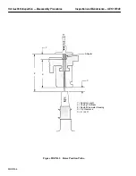
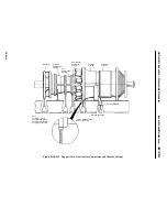
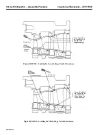
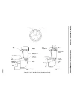
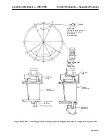
3. Take the concentricity readings as shown on Inspection Form PGS/GT-FF-6097 and Figure
HGP-D.11. Record all readings on the Inspection Form. Report readings to your General Electric
Company Field Service Representative for evaluation and disposition.
Note:
The first-stage nozzle is to be concentric with the support ring hot gas
path within a tolerance of 0.050 in., taking into account any ellipticity
in the nozzle assembly. See the alignment diagram in the Reference
Drawing section of this Service Manual.
Operation 11 — How to Remove Upper Half First Stage Nozzle (With Support Pad and Retainer)
Note:
There are two types of first-stage nozzle arrangements presently in use,
one type uses a support pad seal and a seal retainer for each segment
when assembled to the support ring. The second type is known as a uni-
versal first-stage nozzle arrangement and has a tangential support pin
assembly consisting off an offset bushing, support pin, retainer and
lockplate for each segment when assembled to the support ring.
Summary of Contents for MS6001B
Page 2: ...Gas Turbine Inspection and Maintenance GEK 107048 I 2 THIS PAGE INTENTIONALLY LEFT BLANK ...
Page 4: ...Inspection and Maintenance Note THIS PAGE INTENTIONALLY LEFT BLANK ...
Page 13: ...INSERT TAB INTRODUCTION ...
Page 14: ......
Page 25: ...INSERT TAB STANDARD PRACTICES ...
Page 26: ......
Page 87: ...INSERT TAB AUXILIARY CONTROLS SYSTEMS MAINTENANCE ...
Page 88: ......
Page 133: ...INSERT TAB SCHEDULED TURBINE MAINTENACE ...
Page 134: ......
Page 157: ...INSERT TAB COMBUSTION INSPECTION ...
Page 158: ......
Page 239: ...INSERT TAB HOT GAS PATH INSPECTION ...
Page 240: ......
Page 313: ...INSERT TAB MAJOR INSPECTION ...
Page 314: ......
Page 316: ...Inspection and Maintenance GEK 107048 Major Inspection 2 THIS PAGE INTENTIONALLY LEFT BLANK ...
Page 363: ...INSERT TAB MAINTENANCE FORMS ...
Page 364: ......

