Inspection and Maintenance — GEK 107048
Hot Gas Path Inspection — Disassembly Procedures
HGP-D-22
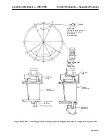
Operation 15 — How to Remove Lower Half First Stage Nozzle (With Tangential Support Pin)
1. Remove the tangential support bolts and retainer plates. Discard bolts and retainer plates.
2. Remove the support pins by breaking the contact between the pin and bushing with a wrench and
withdrawing the pins by means of the threaded extraction hole in the center of the support pin.
3. Remove the horizontal support blocks from the left and right side. Identify the support blocks for
left and right side location
4. Roll out the lower half nozzle by attaching one end to a hook with a straight cable and attaching
the other end to a one ton comealong or chainfall. By alternately raising on the cable and lowering
on the chainfall, the retaining ring and nozzle can be rotated 90
°
.
5. Reattach the chainfall to pickup the nozzle at its vertical centerline. Continue the roll out process
until the nozzle can be lifted clear of the unit.
6. Set the nozzle flat on a piece of plywood or equivalent to protect it from damage.
Operation 16 — How to Remove Lower Half Second and Third Stage Nozzle Radial Retaining
Pins
Note:
The second stage nozzle radial retaining pins are secured to the turbine
casing by threaded plugs which are screwed into the casing, each plug
is staked in two places.
The third stage nozzle radial retaining pins are held in position by
plates secured to the turbine casing by hex bolts with lockplates.
1. Remove all the second stage nozzle radial retaining pins, if pins are not stamped as to location,
stamp the location upon removal.
2. Remove the holding plates which position the radial third stage nozzle retaining pins. Remove
the retaining pins, if pins are not stamped as to location, stamp them upon removal.
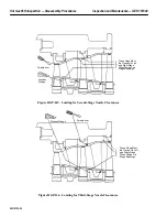
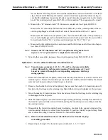
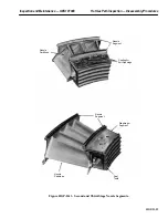
Operation 17 — How to Remove Lower Half Second and Third Stage Nozzle Segments
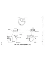
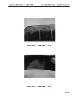
(See Figure HGP-D.13)
1. Each nozzle segment can be removed from the turbine casing by rolling it out individually on its
outer sidewall forward and aft hook fits. Each diaphragm segment is removed along with its adja-
cent nozzle segment as one piece. Mark each segment per Inspection Form PGS/GT-FF-6102 and
PGS/GT-FF-6099 numbering sequence.
Summary of Contents for MS6001B
Page 2: ...Gas Turbine Inspection and Maintenance GEK 107048 I 2 THIS PAGE INTENTIONALLY LEFT BLANK ...
Page 4: ...Inspection and Maintenance Note THIS PAGE INTENTIONALLY LEFT BLANK ...
Page 13: ...INSERT TAB INTRODUCTION ...
Page 14: ......
Page 25: ...INSERT TAB STANDARD PRACTICES ...
Page 26: ......
Page 87: ...INSERT TAB AUXILIARY CONTROLS SYSTEMS MAINTENANCE ...
Page 88: ......
Page 133: ...INSERT TAB SCHEDULED TURBINE MAINTENACE ...
Page 134: ......
Page 157: ...INSERT TAB COMBUSTION INSPECTION ...
Page 158: ......
Page 239: ...INSERT TAB HOT GAS PATH INSPECTION ...
Page 240: ......
Page 313: ...INSERT TAB MAJOR INSPECTION ...
Page 314: ......
Page 316: ...Inspection and Maintenance GEK 107048 Major Inspection 2 THIS PAGE INTENTIONALLY LEFT BLANK ...
Page 363: ...INSERT TAB MAINTENANCE FORMS ...
Page 364: ......


