Inspection and Maintenance — GEK 107048
Hot Gas Path Inspection — Reassembly Procedures
HGP-R-4
Note:
Check to insure that the groove in the first stage nozzle support ring is
clean and there are no burrs on the tongue or in the groove prior to roll-
ing in lower half first stage nozzle.
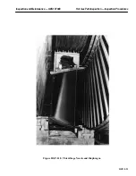
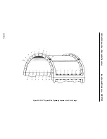
4. If the unit’s rotor is in place, begin rolling the nozzle half assembly into the turbine casing by let-
ting out on one chainfall and taking up on the other, moving the crane as necessary to lead the
assembly around the rotor.
5. Continue the roll-in process by taking up on the leading end cable and letting out on the following
end cable.
6. By the time the nozzle half horizontal joints are oriented in the horizontal plane, both cable slings
will be attached to the eyebolts previously installed in the horizontal joint bolt holes. With the
chainfalls attached to the cable slings, lift the first stage nozzle half slightly and install the hori-
zontal support blocks under the flanges.
Note:
Be sure that the horizontal joint support blocks are replaced in their
original positions. These blocks are ground at factory assembly of the
turbine to obtain the proper clearances for first-stage nozzle concen-
tricity.
7. Lower the first stage nozzle half onto the horizontal joint blocks and remove the lifting slings,
chainfalls and eyebolts.
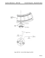
8. Apply a light coating of Fel Pro C-102 anti seize compound to the tangential support pins and
install the pins into the support ring and first-stage nozzle support lugs.
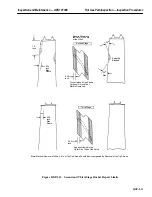
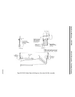
9. Assemble the support pin retainer plate, coat the retainer plates bolts with anti seize compound,
install and tighten the bolts. Bend the locking tabs on the retainer plates to keep the bolts from
rotating. See Figure HGP-R.2.
10. Assemble the horizontal joint clamps, bolt them securely and record the clearances. Record the
nozzle-to-rotor clearance on Inspection Form PGS/GT-FF-6105. Refer to the Unit Clearance
Diagram in the Reference Drawing section of this Service Manual for clearance specifications.
It is recommended that all turbine clearances taken should be submitted to your local General
Electric Company Field Service Representative, prior to reassembly of turbine casing.
11. The eccentric pin is to be fitted to the first stage nozzle lower half after the nozzle has been as-
sembled and properly positioned but before the upper half casing is installed.
If the nozzle was not replaced and no adjustments were made to achieve proper clearance, the
eccentric pin should seat properly without any adjustments. However if the nozzle was replaced
or adjusted, the following procedure is to be used.
a. Cut the old retaining strap from the top of the eccentric pin heads and grind both surfaces
smooth.
b. Install the eccentric pin into the casing to its full depth carefully as not to disturb the lateral
centering of the nozzles.
c. Coat top portion of the pin with Dykem Blue.
Summary of Contents for MS6001B
Page 2: ...Gas Turbine Inspection and Maintenance GEK 107048 I 2 THIS PAGE INTENTIONALLY LEFT BLANK ...
Page 4: ...Inspection and Maintenance Note THIS PAGE INTENTIONALLY LEFT BLANK ...
Page 13: ...INSERT TAB INTRODUCTION ...
Page 14: ......
Page 25: ...INSERT TAB STANDARD PRACTICES ...
Page 26: ......
Page 87: ...INSERT TAB AUXILIARY CONTROLS SYSTEMS MAINTENANCE ...
Page 88: ......
Page 133: ...INSERT TAB SCHEDULED TURBINE MAINTENACE ...
Page 134: ......
Page 157: ...INSERT TAB COMBUSTION INSPECTION ...
Page 158: ......
Page 239: ...INSERT TAB HOT GAS PATH INSPECTION ...
Page 240: ......
Page 313: ...INSERT TAB MAJOR INSPECTION ...
Page 314: ......
Page 316: ...Inspection and Maintenance GEK 107048 Major Inspection 2 THIS PAGE INTENTIONALLY LEFT BLANK ...
Page 363: ...INSERT TAB MAINTENANCE FORMS ...
Page 364: ......

