Inspection and Maintenance — GEK 107048
Combustion Inspection — Inspection Procedures
CI-I-26
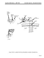
5. When the spark plug is installed on the turbine, follow the assembly instructions on the combustion
arrangement drawing and tighten the swagelock fitting at that time.
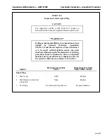
**WARNING**
If this gas turbine installation is in a hazardous area as
defined by National Protection Association
(NFPA)–70, and the site requires a Class I, Division 1
or 2, Group D certified ignition system, any parts
which are replaced as part of maintenance or servicing
procedures must be identical to those as originally
installed, per General Electric Company in order for
the system certification to continue to be in effect.
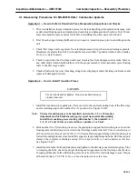
Operation 13 — How to Inspect and Test the Flame Detectors
Note:
The flame detector tube is contained in the flame sensor subassembly.
Combined with the body and window subassembly, the two subassem-
blies form the ultraviolet flame sensor. If during inspection and testing
the sensor is found to be faulty, it should be replaced as a complete as-
sembly.
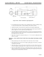
1. Clean the scanner lenses. Reconnect flame detector wiring and energize the control panel. With
power on the control panel, check that FL-1 and FL-2 indicating lights are on.
CAUTION
Reverse polarity will destroy the detector.
1. With the detector amplifier power on, verify base wir-
ing polarity at the sensor junction box by reading 290
VDC (minimum) across leak pair.
2. Turn power off and connect black detector lead to plus
(+) and the white lead to minus (–).
2. Using an ultraviolet source at the sensor, assure that each flame detector picks up and drops out
when ultraviolet source is placed in front of the sensor and removed.
Note:
A high level of ultraviolet is defined as a match or candle at a distance
of less than 2 in. The unit, however, should be capable of detecting a
match or candle at approximately 18 in.
Summary of Contents for MS6001B
Page 2: ...Gas Turbine Inspection and Maintenance GEK 107048 I 2 THIS PAGE INTENTIONALLY LEFT BLANK ...
Page 4: ...Inspection and Maintenance Note THIS PAGE INTENTIONALLY LEFT BLANK ...
Page 13: ...INSERT TAB INTRODUCTION ...
Page 14: ......
Page 25: ...INSERT TAB STANDARD PRACTICES ...
Page 26: ......
Page 87: ...INSERT TAB AUXILIARY CONTROLS SYSTEMS MAINTENANCE ...
Page 88: ......
Page 133: ...INSERT TAB SCHEDULED TURBINE MAINTENACE ...
Page 134: ......
Page 157: ...INSERT TAB COMBUSTION INSPECTION ...
Page 158: ......
Page 239: ...INSERT TAB HOT GAS PATH INSPECTION ...
Page 240: ......
Page 313: ...INSERT TAB MAJOR INSPECTION ...
Page 314: ......
Page 316: ...Inspection and Maintenance GEK 107048 Major Inspection 2 THIS PAGE INTENTIONALLY LEFT BLANK ...
Page 363: ...INSERT TAB MAINTENANCE FORMS ...
Page 364: ......


