Hot Gas Path Inspection — Disassembly Procedures
Inspection and Maintenance — GEK 107048
HGP-D-5
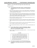
Operation 5 — How to Place Mechanical Support Jacks Under Turbine Casing
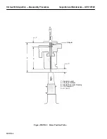
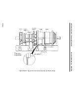
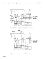
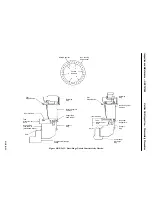
(See Figure HGP-D.2)
Note:
The base floorplate underneath the compressor and turbine flanges has
removeable floorplate cut outs at each location for a mechanical sup-
port jack.
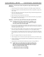
1. Remove the turbine compartment floor plate covers, provided beneath the vertical flange joints,
so that the concrete foundation can be used as the jacking support surface. Ensure jacks are
mounted perpendicular to the gas turbine.
2. Install a mechanical support jack between the jacking platform and the concrete base beneath the
turbine to exhaust frame flanges and tighten the jack up against the platform. Mount a second jack
between the jacking platform and the turbine to exhaust frame flanges and snug the jack up
against the flange. See Figure HGP-D.2 position number 2.
3. Mount a dial indicator, separate from the jack, to measure upward jacking deflection of the ex-
haust frame flange. Set dial indicator to zero.
4. Install a mechanical support jack at the bottom centerline flange of the compressor discharge to
turbine casing flange and snug the jack up against the flange. See Figure HGP-D.2 position num-
ber 3.
5. Mount a dial indicator, separate from the jack, to measure upward jacking deflection of the com-
pressor discharge to turbine casing flange. Set dial indicator to zero.
6. Jack the turbine/exhaust frame flange to 0.004 in.
±
0.001 in. and record both dial indicator read-
ings.
Note:
If upon reaching a flange to be jacked, the dial indicator reading al-
ready exceeds the value to be jacked to, then only snug the jack to the
flange and record all dial indicator readings
7. Jack the compressor discharge/turbine casing flange to 0.002 in. — 0.003 in. and record both dial
indicator readings.
CAUTION
If for any reason during the hot gas path inspection it be-
comes necessary to remove the compressor discharge cas-
ing and or the compressor casing(s) mechanical support
jacks must be installed under these casings and the for-
ward flange of the inlet bell housing. Refer to the Major
Inspection Section in this instruction for location of the
jacks and the jacking instructions.
Note:
Do not, under any circumstances, remove the mechanical support jacks
or dial indicators until all upper half casings have been reinstalled and
bolted up.
Summary of Contents for MS6001B
Page 2: ...Gas Turbine Inspection and Maintenance GEK 107048 I 2 THIS PAGE INTENTIONALLY LEFT BLANK ...
Page 4: ...Inspection and Maintenance Note THIS PAGE INTENTIONALLY LEFT BLANK ...
Page 13: ...INSERT TAB INTRODUCTION ...
Page 14: ......
Page 25: ...INSERT TAB STANDARD PRACTICES ...
Page 26: ......
Page 87: ...INSERT TAB AUXILIARY CONTROLS SYSTEMS MAINTENANCE ...
Page 88: ......
Page 133: ...INSERT TAB SCHEDULED TURBINE MAINTENACE ...
Page 134: ......
Page 157: ...INSERT TAB COMBUSTION INSPECTION ...
Page 158: ......
Page 239: ...INSERT TAB HOT GAS PATH INSPECTION ...
Page 240: ......
Page 313: ...INSERT TAB MAJOR INSPECTION ...
Page 314: ......
Page 316: ...Inspection and Maintenance GEK 107048 Major Inspection 2 THIS PAGE INTENTIONALLY LEFT BLANK ...
Page 363: ...INSERT TAB MAINTENANCE FORMS ...
Page 364: ......

