Inspection and Maintenance — GEK 107048
Combustion Inspection — Reassembly Procedures
CI-R-14
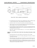
5. Tighten bolts until the gap between the boss and the seal ring is 0.080
±
0.015 all the way around
the boss. This ensures the proper compression on the packing rings.
Operation 5 — How to Install the Inner Crossfire Tubes and Cap and Liner Assemblies
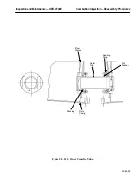
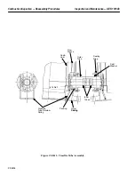
1. Insert the two inner crossfire tubes into the outer crossfire tube with the male and female ends
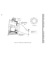
oriented as shown on the combustion arrangement drawing, see Figure CI-R.12 and CI-R.13.
This orientation should be maintained all the way around the turbine.
2. Insert the crossfire tube retainers part way to keep the tubes in place.
3. To install a cap and liner assembly, it will be necessary to retract both crossfire tube ends. This
can be done by pushing the crossfire tube ends toward the adjacent chambers and holding them
back with the retainers partially inserted on the end of the tube.
4. Slide the appropriate liner into the outer casing until it engages the transition piece and the three
liner stops. Be sure the liner has reached the aft limit of the liner stops.
5. Remove the crossfire tube retainers, insert the crossfire tube ends into the crossfire collars, and
reinsert the retainers in the grooves provided in the tubes.
Operation 6 — How to Assemble the Primary Flame Detectors and Spark Plugs To Outer
Combustion Casings
Note:
Primary Flame detectors are located in chamber 2, 3, 7 and 8. Spark
plugs are located in chamber number 1 and 10.
Note:
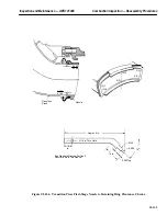
If the spark plug or liner have not been replaced, the spark plug assem-
bly may be replaceable without adjustment. See the Spark Plug Assem-
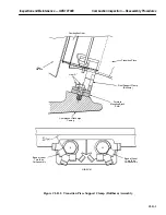
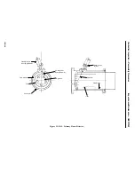
bly for the proper position of the ignitor tip (Figure CI-R.14). The tip
must be 0.380 inside the liner measured from the liner outside surface.
The tip must also be centered in the hole in the liner to prevent wear.
If either of the above cannot be met, use the following procedure.
1. Remove ignitor assembly from base assembly and install base assembly on casing boss using a
new gasket.
2. Slide the ignitor assembly into the base assembly through the slot in the flow sleeve down to the
liner. With the liner seated in the downstream direction against the liner stops, attempt to slide
the ignitor through the liner hole. If the ignitor is not centered in the hole, loosen the bolts that
compress the ball joint packings, and adjust the ignitor until it is centered in the hole. Then retigh-
ten the ball joint packing bolts.
3. Slide the ignitor into the liner until the tip is 0.380
±
0.30 past the outside surface of the cap and
liner, see Figure CI-R.14.
4. The Swageloc fitting may then be locked on to the ignitor.
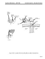
5. Mount the flame detector support on the combustion outer casing as called out on the combustion
arrangement.
Summary of Contents for MS6001B
Page 2: ...Gas Turbine Inspection and Maintenance GEK 107048 I 2 THIS PAGE INTENTIONALLY LEFT BLANK ...
Page 4: ...Inspection and Maintenance Note THIS PAGE INTENTIONALLY LEFT BLANK ...
Page 13: ...INSERT TAB INTRODUCTION ...
Page 14: ......
Page 25: ...INSERT TAB STANDARD PRACTICES ...
Page 26: ......
Page 87: ...INSERT TAB AUXILIARY CONTROLS SYSTEMS MAINTENANCE ...
Page 88: ......
Page 133: ...INSERT TAB SCHEDULED TURBINE MAINTENACE ...
Page 134: ......
Page 157: ...INSERT TAB COMBUSTION INSPECTION ...
Page 158: ......
Page 239: ...INSERT TAB HOT GAS PATH INSPECTION ...
Page 240: ......
Page 313: ...INSERT TAB MAJOR INSPECTION ...
Page 314: ......
Page 316: ...Inspection and Maintenance GEK 107048 Major Inspection 2 THIS PAGE INTENTIONALLY LEFT BLANK ...
Page 363: ...INSERT TAB MAINTENANCE FORMS ...
Page 364: ......

