Standard Practices
Inspection and Maintenance
SP–4
(2) Instant Seal Locktite Plastic Gasket shall be used on all bolted oil to air joints (vertical and
horizontal) that are not gasketed and on plug openings. This includes, but is not limited to,
bearing housings, continuously lubricated coupling guards and stationary oil seals.
Instant Seal Locktite Plastic Gasket shall not be used on vertical joints of non-bolted stationary
oil seals.
b. Joint compound shall not be used on sheet metal joints except as follows:
(1) Gasket tape used between exhaust skin, or plenum joints shall be coated on both sides with
perfect seal.
(2) Silicone rubber adhesive sealant shall be used between non-gasketed joints of inlet hoods
or plenums. It shall be applied as a continuous bead of minimum of 0.25 wide and shall be
tangent to the outboard edges of the flange bolt holes.
20. Piping Flanges
a. Pipe flanges must not be forced into alignment. If flanges cannot be brought to within 1/8 in.
of parallel by hand, the piping should be reformed or replaced. When the flanges are parallel
with a new gasket in place, insert the bolts by hand. Do not pry on the flanges. Use anti-seize
compound on the bolts. Tighten the bolts in three stages on alternately opposite bolts.
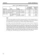
21. Bolt and Stud Torquing
a. Before torquing, remove foreign matter from bolt, nut and bolting surfaces.
b. Apply anti-seize compound to bolt and nut threads and bearing surfaces.
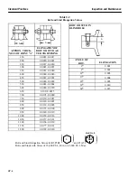
c. Tighten bolt/or nut to be sure threads are free, then back off until free from surface. Snug against
surface and torque to values shown in Table 2-1.
d. When using impact wrenches, torque to values in Table 2-1. Item 21-C above does not apply
to impact wrenching.
22. Classification of Joints
a. All classes of joints (oil tight, air tight and for frame rigidity) with metal to metal contact shall
have their bolt or stud elongation determined by micrometer measurements, torque wrench or
by head rotation. See Table 2-1 and 2-2.
b. All gasket joints shall have their bolt and stud elongation determined by micrometer measure-
ments or torque wrench. See Tables 2-1 and 2-2.
c. To insure air tight joints there must be a 50% contact over the critical area. Burrs and high spots
must be removed before assembly.
d. To insure an oil tight joint, a line of continuous contact, with 0.25 in. minimum width, must be
maintained, in addition to 50% contact over the critical area. The 50% contact must be equally
distributed over the critical area. See Figure 2-1.
Summary of Contents for MS6001B
Page 2: ...Gas Turbine Inspection and Maintenance GEK 107048 I 2 THIS PAGE INTENTIONALLY LEFT BLANK ...
Page 4: ...Inspection and Maintenance Note THIS PAGE INTENTIONALLY LEFT BLANK ...
Page 13: ...INSERT TAB INTRODUCTION ...
Page 14: ......
Page 25: ...INSERT TAB STANDARD PRACTICES ...
Page 26: ......
Page 87: ...INSERT TAB AUXILIARY CONTROLS SYSTEMS MAINTENANCE ...
Page 88: ......
Page 133: ...INSERT TAB SCHEDULED TURBINE MAINTENACE ...
Page 134: ......
Page 157: ...INSERT TAB COMBUSTION INSPECTION ...
Page 158: ......
Page 239: ...INSERT TAB HOT GAS PATH INSPECTION ...
Page 240: ......
Page 313: ...INSERT TAB MAJOR INSPECTION ...
Page 314: ......
Page 316: ...Inspection and Maintenance GEK 107048 Major Inspection 2 THIS PAGE INTENTIONALLY LEFT BLANK ...
Page 363: ...INSERT TAB MAINTENANCE FORMS ...
Page 364: ......


