Inspection and Maintenance — GEK 107048
Major Inspection — Inspection Procedures
MI-I-6
11. Coat the lower half number two bearing liner to be installed with clean turbine oil used in the unit
lube system and set the liner on the rotor journal. Roll the bearing liner carefully into the lower
half of the bearing housing. Restrain the liner from falling into the lower half.
CAUTION
To avoid deleterious effects, use of additives with gas tur-
bine lubricant or in areas wetted by the lubricant should be
limited to those approved by the fluid supplier or Fluid
Systems Engineering of the Gas Turbine Division of the
General Electric Company. If there are any questions or
doubts about a material, contact your General Electric
Company Field Service Representative.
12. With the lower half number two bearing liner installed and positioned, carefully release the rotor
support lever and gently lower the rotor journal to rest on the lower bearing liner.
13. Recover the number two bearing housing to protect the bearing journal and keep foreign matter
out of the housing.
14. Support the rotor in the number one bearing area with a suitable jack to raise the shaft for the re-
moval of the lower half number one bearing liner.
15. Mount a dial indicator at the bearing liner centerline, using the jack raise the shaft 0.014 in. maxi-
mum to release the pressure on the bearing liner.
16. Repeat disassembly and inspection steps three (3) through ten (10) for the number one bearing
liner.
17. Coat the lower half number one bearing liner to be installed with clean turbine oil used in the unit
lube system and set the liner on the journal. Roll the bearing liner carefully into the lower half
of the bearing housing. Restrain the liner from falling into the lower half.
18. With the lower half number one bearing liner installed and positioned, carefully release the rotor
support jack and gently lower the rotor journal to rest on the lower bearing liner.
19. Recover the number one bearing housing to protect the bearing journal and keep foreign matter
out of the housing.
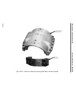
20. Thrust bearings just as with journal bearings, the babbitt surfaces must be inspected for cracks,
chips, scratches,and wiping. Cracks or chips must be eliminated before the turbine is placed back
in operation. Scratches or pits that are not over 0.005 in. deep, pits that are not over 0.100 in. in
diameter and pits or scratches that do not extend radially more than 1/2 in., one per pad are accept-
able. Raised metal is not allowed.
Note:
The cumulative width of all scratches in circumferential and radial di-
rections should not exceed 0.100 in. (Radial or axial in-line pit forma-
tions exceeding three in number must be counted as continuous
scratches.)
Summary of Contents for MS6001B
Page 2: ...Gas Turbine Inspection and Maintenance GEK 107048 I 2 THIS PAGE INTENTIONALLY LEFT BLANK ...
Page 4: ...Inspection and Maintenance Note THIS PAGE INTENTIONALLY LEFT BLANK ...
Page 13: ...INSERT TAB INTRODUCTION ...
Page 14: ......
Page 25: ...INSERT TAB STANDARD PRACTICES ...
Page 26: ......
Page 87: ...INSERT TAB AUXILIARY CONTROLS SYSTEMS MAINTENANCE ...
Page 88: ......
Page 133: ...INSERT TAB SCHEDULED TURBINE MAINTENACE ...
Page 134: ......
Page 157: ...INSERT TAB COMBUSTION INSPECTION ...
Page 158: ......
Page 239: ...INSERT TAB HOT GAS PATH INSPECTION ...
Page 240: ......
Page 313: ...INSERT TAB MAJOR INSPECTION ...
Page 314: ......
Page 316: ...Inspection and Maintenance GEK 107048 Major Inspection 2 THIS PAGE INTENTIONALLY LEFT BLANK ...
Page 363: ...INSERT TAB MAINTENANCE FORMS ...
Page 364: ......


