Combustion Inspection — Disassembly Procedures
Inspection and Maintenance — GEK 107048
CI-D-13
Operation 11 — How to Remove the Eleventh Stage Cooling and Sealing Air Lines
1. Unbolt the upper half 11th-stage cooling and sealing air piping from the bottom flange on the 5th
to 11th stage bearing seal valve (VA14, if applicable), the compressor casing and the branch off
flange of the compressor bleed valve (VA2-2).
2. Remove the piping and cover all openings. Identify and tag any orifices removed for location.
3. Unbolt the lower half 11th stage cooling and sealing air line from the compressor casing lower
half and the branch off flange of the piping to the compressor bleed valve (VA2-1).
4. Remove the piping and cover all openings.
Operation 12 — Remove Fuel Nozzle – End Cover Assemblies
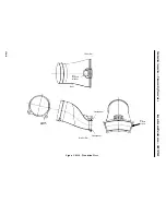
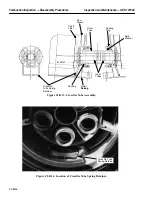
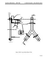
1. Install two or three eyebolts in the top (number 10) end cover and rig so that the cover will hang
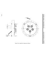
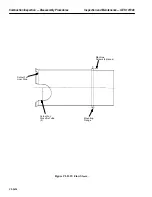
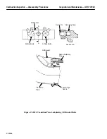
in the proper orientation angle to its mating flange. See Figure CI-D.11.
2. Attach cables to eyebolts and adjust so that cover will not swing or tilt during removal.
CAUTION
Fabricated end cover – fuel nozzle assembly weighs
approximately 400 pounds (180 kilograms).
Cast end cover – fuel nozzle assembly weighs approxi-
mately 160 pounds (75 kilograms).
3. Make sure three guide pins (Figure CI-D.11) are in place in the cover and that their retaining nuts
are tight.
4. Remove all flange bolts. The cover is now supported by the guide pins.
5. Raise crane hook to support end cover weight.
6. If the cover moves, slide it axially on guide pins. If it will not move, install three jacking bolts
in threaded holes between guide pins.
7. Use jack bolts to move the cover axially until rabbet is free (1/4 inch) and the gas swirl tips are
free of the cap collars (1/2 inch).
8. Then slide the end cover axially until the guide pins clear the combustion casing flange.
9. At this point, the cover assembly can be moved away and lifted clear of the turbine.
CAUTION
The fuel nozzles are precision–machined parts. Do not al-
low them to hit any part of the turbine.
Summary of Contents for MS6001B
Page 2: ...Gas Turbine Inspection and Maintenance GEK 107048 I 2 THIS PAGE INTENTIONALLY LEFT BLANK ...
Page 4: ...Inspection and Maintenance Note THIS PAGE INTENTIONALLY LEFT BLANK ...
Page 13: ...INSERT TAB INTRODUCTION ...
Page 14: ......
Page 25: ...INSERT TAB STANDARD PRACTICES ...
Page 26: ......
Page 87: ...INSERT TAB AUXILIARY CONTROLS SYSTEMS MAINTENANCE ...
Page 88: ......
Page 133: ...INSERT TAB SCHEDULED TURBINE MAINTENACE ...
Page 134: ......
Page 157: ...INSERT TAB COMBUSTION INSPECTION ...
Page 158: ......
Page 239: ...INSERT TAB HOT GAS PATH INSPECTION ...
Page 240: ......
Page 313: ...INSERT TAB MAJOR INSPECTION ...
Page 314: ......
Page 316: ...Inspection and Maintenance GEK 107048 Major Inspection 2 THIS PAGE INTENTIONALLY LEFT BLANK ...
Page 363: ...INSERT TAB MAINTENANCE FORMS ...
Page 364: ......

