


24.3 Functional overview
0xC520
0xD928
Fast
Fn Test
Clock
Allow update for N bus
clk cycles
N
b
us
clk
cy
cle
s
LPO
N bus clk cycles
Refresh Sequence
2 writes of data within K
bus clock cycles of each
other
Unlock Sequence
2 Writes of data within K bus clock
cycles of each other
Disable Control/Configuration
bit changes N bus clk cycles after
unlocking
WDOGEN = WDOG Enable
WINEN = Windowed Mode Enable
WDOGT = WDOG Time-out Value
WDOGCLKSRC = WDOG Clock Source
WDOG Test = WDOG Test Mode
WAIT EN = Enable in wait mode
STOP EN = Enable in stop mode
Debug EN = Enable in debug mode
SRS = System Reset Status Register
R = Timer Reload
WDOG
reset count
Alt Clock
Osc
WDOG
Clock
Selection
WDOG CLK
R
System reset
and SRS register
Interrupt
IRQ_RST_
EN = = 1?
Invalid
Unlock Seq
32-bit Timer
Timer Time-out
Refresh
Outside
Window
Invalid Refresh
Seq
No config
after unlocking
No unlock
after reset
0xB480
0xA602
System
Bus Clock
32-bit Modulus Reg
(Time-out Value)
DebugEN
Window_begin
WDOGTEST
STOPEN
WAITEN
WDOGT
WDOG
CLKSRC
WINEN
WDOGEN
WDOG
Y
N
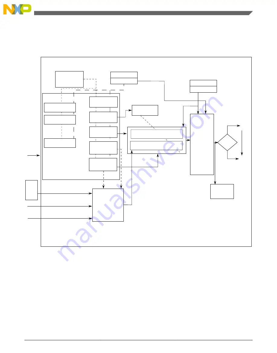
Figure 24-1. WDOG operation
The preceding figure shows the operation of the watchdog. The values for N and K are:
• N = 256
• K = 20
The watchdog is a fail safe mechanism that brings the system into a known initial state in
case of its failure due to CPU clock stopping or a run-away condition in code execution.
In its simplest form, the watchdog timer runs continuously off a clock source and expects
Chapter 24 Watchdog Timer (WDOG)
K22F Sub-Family Reference Manual , Rev. 3, 7/2014
Freescale Semiconductor, Inc.
513


