Chapter 8 DMA Controller
8-3
8.3 Detailed
Explanation
8.3.1 Transfer
Mode
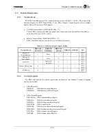
The DMA Controller supports five transfer mode types (refer to Table 8.3.1 below). The setting of the
External Request bit (DMCCRn.EXTRQ) of the DMA Channel Control Register selects whether
transfer with an I/O device is a DMA transfer.
•
I/O DMA Transfer Mode (DMCCRn.EXTRQ = “1”)
Perform DMA transfer with either an external device connected to the External Bus Controller or
an on-chip I/O device (ACLC or SIO).
•
Memory Transfer Mode (DMCCRn.EXTRQ = “0”)
Either copies data between memory devices or fills data in memory.
Table 8.3.1 DMA Controller Transfer Modes
Transfer Mode
DMCCRn
EXTREQ
DRQCTR
DMAREQn
DMCCRn
SNGAD
DMSAR DMDAR Ref.
External I/O
(Single Address)
1 0xxxx 1
√
-
8.3.3
8.3.7
External I/O
(Dual Address)
1 0xxxx 0
√
√
8.3.3
8.3.8
Internal I/O
1
10xx (SIO)
11xx (ACLC)
0
√
√
8.3.4
8.3.8
Memory-Memory Copy
0
-
0
√
√
8.3.4
8.3.8
Fill Memory
0
-
1
√
-
8.3.6
8.3.7
8.3.2 On-chip
Registers
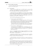
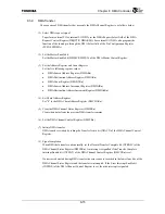
The DMA Controller has two shared registers that are shared by four channels. Section 8.4 explains
each register in detail.
•
Shared Registers
DMMCR:
DMA Master Control Register
DMMFDR:
DMA Memory Fill Data Register
•
DMA Channel Register
DMCHARn:
DMA Chained Address Register
DMSARn:
DMA Source Address Register
DMDARn: DMA
Destination
Address
Register
DMCNTRn: DMA
Count
Register
DMSAIRn:
DMA Source Address Increment Register
DMDAIRn:
DMA Destination Address Increment Register
DMCCRn:
DMA Channel Control Register
DMCSRn:
DMA Channel Status Register
Содержание TMPR4925
Страница 1: ...64 Bit TX System RISC TX49 Family TMPR4925 Rev 3 0 ...
Страница 4: ......
Страница 15: ...Handling Precautions ...
Страница 16: ......
Страница 18: ...1 Using Toshiba Semiconductors Safely 1 2 ...
Страница 40: ...3 General Safety Precautions and Usage Considerations 3 18 ...
Страница 42: ...4 Precautions and Usage Considerations 4 2 ...
Страница 43: ...TMPR4925 ...
Страница 44: ......
Страница 54: ...Chapter 1 Features 1 8 ...
Страница 58: ...Chapter 2 Block Diagram 2 4 ...
Страница 88: ...Chapter 4 Address Mapping 4 12 ...
Страница 226: ...Chapter 8 DMA Controller 8 58 ...
Страница 260: ...Chapter 9 SDRAM Controller 9 34 ...
Страница 480: ...Chapter 15 Interrupt Controller 15 32 ...
Страница 554: ...Chapter 19 Real Time Clock RTC 19 8 ...
Страница 555: ...Chapter 20 Removed 20 1 20 Removed ...
Страница 556: ...Chapter 20 Removed 20 2 ...
Страница 564: ...Chapter 21 Extended EJTAG Interface 21 8 ...
Страница 580: ...Chapter 22 Electrical Characteristics 22 16 ...
Страница 586: ...Chapter 23 Pin Layout Package 23 6 23 2 Package Package Type Package Code 256 pin PBGA PBGA 4L P BGA256 2727 1 27A4 ...
Страница 588: ...Chapter 24 Usage Notes 24 2 ...
Страница 590: ...Appendix A TX49 H2 Core Supplement A 2 ...


