Chapter 17 Serial Peripheral Interface
17-11
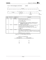
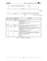
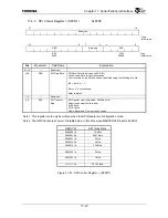
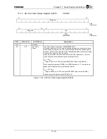
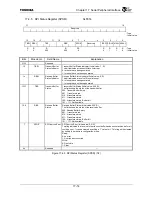
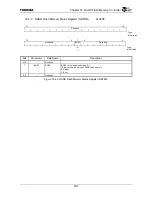
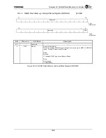
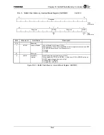
Bits Mnemonic Field
Name
Explanation
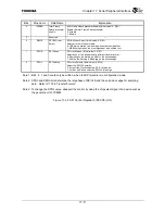
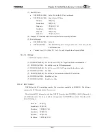
4 IFSPSE
Inter Frame
Space prescaler
enable
Inter Frame Space prescaler Enable (Initial value: 0, R/W)
Enable the Inter Frame Space prescaler.
0: Disable
1: Enable
3
⎯
Reserved
⎯
2
SBOS
SPI Bit Order
Select
SPI Bit Order Select (Initial value: 0, R/W)
Select bit order of transfer data.
0: LSB first operation, the least significant bit is shifted first.
1: MSB first operation, the most significant bit is shifted first.
1 SPHA
SPI
Phase
SPI clock Phase (Initial value: 0, R/W)
Selects one of two fundamentally different transfer format.
0: Sampling on the first edge, Shift on the second edge.
1: Shift on the first edge, Sampling on the second edge.
0 SPOL
SPI
Polarity
SPI clock Polarity (Initial value: 0, R/W)
Select the SPICLK polarity.
0: Active High Clocks selected; SPICLK idles low
1: Active Low Clocks selected; SPICLK idles high
Note 1: Bit 4, 2, 1 and 0 could only be written, when the SPI module is in configuration mode.
Note 2: SPOL and SPHA bits determine the idle phase of SPICLK and the valid clock edge for sampling
data. Refer to “17.3.4 Transfer Format”.
Note 3: To change the SPOL value, deassert the control by using the chip select signal of a device such as
the general port of TX4925.
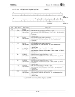
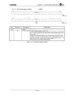
Figure 17.4.2 SPI Control Register 0 (SPCR0) (2/2)
Содержание TMPR4925
Страница 1: ...64 Bit TX System RISC TX49 Family TMPR4925 Rev 3 0 ...
Страница 4: ......
Страница 15: ...Handling Precautions ...
Страница 16: ......
Страница 18: ...1 Using Toshiba Semiconductors Safely 1 2 ...
Страница 40: ...3 General Safety Precautions and Usage Considerations 3 18 ...
Страница 42: ...4 Precautions and Usage Considerations 4 2 ...
Страница 43: ...TMPR4925 ...
Страница 44: ......
Страница 54: ...Chapter 1 Features 1 8 ...
Страница 58: ...Chapter 2 Block Diagram 2 4 ...
Страница 88: ...Chapter 4 Address Mapping 4 12 ...
Страница 226: ...Chapter 8 DMA Controller 8 58 ...
Страница 260: ...Chapter 9 SDRAM Controller 9 34 ...
Страница 480: ...Chapter 15 Interrupt Controller 15 32 ...
Страница 554: ...Chapter 19 Real Time Clock RTC 19 8 ...
Страница 555: ...Chapter 20 Removed 20 1 20 Removed ...
Страница 556: ...Chapter 20 Removed 20 2 ...
Страница 564: ...Chapter 21 Extended EJTAG Interface 21 8 ...
Страница 580: ...Chapter 22 Electrical Characteristics 22 16 ...
Страница 586: ...Chapter 23 Pin Layout Package 23 6 23 2 Package Package Type Package Code 256 pin PBGA PBGA 4L P BGA256 2727 1 27A4 ...
Страница 588: ...Chapter 24 Usage Notes 24 2 ...
Страница 590: ...Appendix A TX49 H2 Core Supplement A 2 ...


