Chapter 3 Signals
3-13
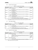
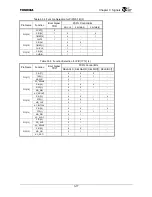
Table 3.2.2 Boot Configuration Specified with the ADDR[19:0], TDO, UAE and SADDR10 Signals (1/2)
Signal Description
Corresponding
Register Bit
Configuration
Determined at
ADDR[19] Reserved
This signal will be set to 0 upon booting.
CCFG bit [12]
RESET
*
deassert
edge
ADDR[18]
PCI Clock Enable
Specifies whether the clock generated by the TX4925 internal clock
generator is used as a PCI clock.
L = Use a PCI clock input from an external device.
The PCI clock is input via PCICLKIO.
PCICLK[2:1] are placed in High-Z state.
H = Use a clock generated by the TX4925 clock generator.
The clock is output from PCICLK[2:1] and PCICLKIO. The clock output
from PCICLKIO is fed back for use with the internal PCIC.
PCFG. PCICLKEN
PON
*
deassert edge
ADDR[17:16] Reserved
Used for testing. Because this signal is used for setting a clock
frequency, ensure that the signal will not be set to 0 upon booting.
CCFG.bit[18](ADDR[
17])
CCFG.bit[27](ADDR[
16])
PON
*
deassert edge
ADDR[15]
PCI Controller Mode Select
Specifies the operating mode of the TX4925 PCI controller.
L = Satellite
H = Host
CCFG. PCIMODE
RESET
*
deassert
edge
ADDR[14] TX4925
Endian Mode
Specifies the TX4925 endian mode.
L = Little endian
H = Big endian
CCFG. ENDIAN
RESET
*
deassert
edge
ADDR[13:12] Boot ROM Bus Width
Specifies the data bus width when booting from a memory device
connected to the external bus controller.
LL = Reserved
LH = 32 bits
HL = 16 bits
HH = 8 bits
EBCCR0.BSZ
RESET
*
deassert
edge
ADDR[11]
Boot Byte Enable Type
When booting from a memory device connected to the external bus
controller, specifies the function of the BE[3:0]
*
/BWE[3:0]
*
pins upon
booting. Be sure that this bit does not become “0” when booting from
PCI.
L = BE[3:0]
*
(Byte Enable)
H = BWE[3:0]
*
(Byte Write Enable)
EBCCR0.BC
RESET
*
deassert
edge
ADDR[10] Reserved
Used for testing. Setting this signal to 0 disables TCK, TDI, TMS,
TRST
*
and TDO. Ensure that the signal will not be set to 0 upon
booting.
CCFG.bit[31] RESET
*
deassert
edge
ADDR[9] Reserved
This signal will not be set to 0 upon booting.
⎯
RESET
*
deassert
edge
Содержание TMPR4925
Страница 1: ...64 Bit TX System RISC TX49 Family TMPR4925 Rev 3 0 ...
Страница 4: ......
Страница 15: ...Handling Precautions ...
Страница 16: ......
Страница 18: ...1 Using Toshiba Semiconductors Safely 1 2 ...
Страница 40: ...3 General Safety Precautions and Usage Considerations 3 18 ...
Страница 42: ...4 Precautions and Usage Considerations 4 2 ...
Страница 43: ...TMPR4925 ...
Страница 44: ......
Страница 54: ...Chapter 1 Features 1 8 ...
Страница 58: ...Chapter 2 Block Diagram 2 4 ...
Страница 88: ...Chapter 4 Address Mapping 4 12 ...
Страница 226: ...Chapter 8 DMA Controller 8 58 ...
Страница 260: ...Chapter 9 SDRAM Controller 9 34 ...
Страница 480: ...Chapter 15 Interrupt Controller 15 32 ...
Страница 554: ...Chapter 19 Real Time Clock RTC 19 8 ...
Страница 555: ...Chapter 20 Removed 20 1 20 Removed ...
Страница 556: ...Chapter 20 Removed 20 2 ...
Страница 564: ...Chapter 21 Extended EJTAG Interface 21 8 ...
Страница 580: ...Chapter 22 Electrical Characteristics 22 16 ...
Страница 586: ...Chapter 23 Pin Layout Package 23 6 23 2 Package Package Type Package Code 256 pin PBGA PBGA 4L P BGA256 2727 1 27A4 ...
Страница 588: ...Chapter 24 Usage Notes 24 2 ...
Страница 590: ...Appendix A TX49 H2 Core Supplement A 2 ...

