Chapter 14 AC-link Controller
14-31
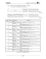
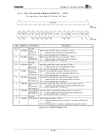
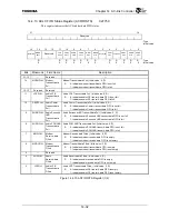
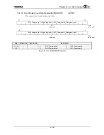
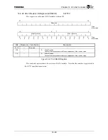
14.4.12 ACLC Slot Disable Register (ACSLTDIS)
0xF74C
This register disables independently the AC-link slot data streams.
31
16
Reserved
: Type
: Initial value
15 10 9 8 7 6 5 4 3 2 1 0
Reserved
GPISLT GPOSLT
MODI
SLT
MODO
SLT
Reserved
AUDI
SLT
LFESLT
CENT
SLT
SURR
SLT
AUDO
SLT
W1C
W1C
W1C
W1C
W1C
W1C
W1C
W1C
W1C :
Type
⎯
⎯
⎯
⎯
⎯
⎯
⎯
⎯
⎯
:
Initial
value
Bits Mnemonic Field
Name
Description
31:10
⎯
Reserved
—
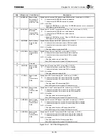
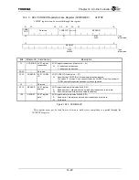
Disable GPI slot reception. (Initial value: –, W1C)
9
GPISLT
Disable GPI slot
reception
W1C 0: No effect
1: Disables GPI slot reception.
Disable GPO Slot transmission. (Initial value: –, W1C)
8 GPOSLT
Disable GPO
Slot
transmission
W1C 0: No effect
1: Disables GPO slot transmission.
Disable Modem slot reception. (Initial value: –, W1C)
7 MODISLT
Disable Modem
slot reception
W1C 0: No effect
1: Disables modem slot reception.
Disable Modem slot transmission. (Initial value: –, W1C)
6 MODOSLT
Disable Modem
slot
transmission
W1C 0: No effect
1: Disables modem slot transmission.
5
⎯
Reserved
—
Disable Audio slot reception. (Initial value: –, W1C)
4 AUDISLT
Disable Audio
slot reception
W1C 0: No effect
1: Disables audio slot reception.
Disable Audio LFE slot transmission. (Initial value: –, W1C)
3 LFESLT
Disable Audio
LFE slot
transmission
W1C 0: No effect
1: Disables audio LFE slot transmission.
Disable Audio Center slot transmission. (Initial value: –, W1C)
2 CENTSLT
Disable Audio
Center slot
transmission
W1C 0: No effect
1: Disables audio Center slot transmission.
Disable Audio Surround L&R slot transmission. (Initial value: –, W1C)
1 SURRSLT
Disable Audio
Surround L&R
slot
transmission
W1C 0: No effect
1: Disables audio Surround L&R slot transmission.
Disable Audio PCM L&R slot transmission. (Initial value: –, W1C)
0 AUDOSLT
Disable
Audio
PCM L&R slot
transmission
W1C 0: No effect
1: Disables audio PCM L&R slot transmission.
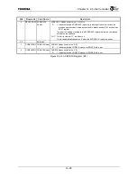
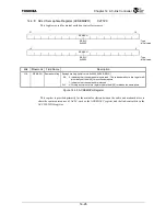
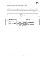
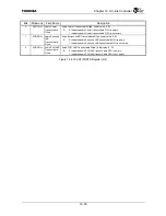
Figure 14.4.9 ACSLTDIS Register
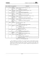
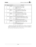
Writing a value into this register needs several BITCLK cycles to take effect. The software must
guarantee that no write access be executed until the previous write access takes effect (completes), by
reading the ACSLTEN.WRPEND bit prior to writing this register. If it is set for a long time, the
BITCLK signal on the AC-link is probably inactive for whatever reason.
Содержание TMPR4925
Страница 1: ...64 Bit TX System RISC TX49 Family TMPR4925 Rev 3 0 ...
Страница 4: ......
Страница 15: ...Handling Precautions ...
Страница 16: ......
Страница 18: ...1 Using Toshiba Semiconductors Safely 1 2 ...
Страница 40: ...3 General Safety Precautions and Usage Considerations 3 18 ...
Страница 42: ...4 Precautions and Usage Considerations 4 2 ...
Страница 43: ...TMPR4925 ...
Страница 44: ......
Страница 54: ...Chapter 1 Features 1 8 ...
Страница 58: ...Chapter 2 Block Diagram 2 4 ...
Страница 88: ...Chapter 4 Address Mapping 4 12 ...
Страница 226: ...Chapter 8 DMA Controller 8 58 ...
Страница 260: ...Chapter 9 SDRAM Controller 9 34 ...
Страница 480: ...Chapter 15 Interrupt Controller 15 32 ...
Страница 554: ...Chapter 19 Real Time Clock RTC 19 8 ...
Страница 555: ...Chapter 20 Removed 20 1 20 Removed ...
Страница 556: ...Chapter 20 Removed 20 2 ...
Страница 564: ...Chapter 21 Extended EJTAG Interface 21 8 ...
Страница 580: ...Chapter 22 Electrical Characteristics 22 16 ...
Страница 586: ...Chapter 23 Pin Layout Package 23 6 23 2 Package Package Type Package Code 256 pin PBGA PBGA 4L P BGA256 2727 1 27A4 ...
Страница 588: ...Chapter 24 Usage Notes 24 2 ...
Страница 590: ...Appendix A TX49 H2 Core Supplement A 2 ...


