Chapter 14 AC-link Controller
14-3
14.3 Functional
Description
ACLC provides four mechanisms to operate AC’97-compliant CODEC(s):
•
AC-link status control (start-up and low-power mode)
•
CODEC register access
•
Sample-data transmission and reception
•
GPIO operation
This section first describes the CODEC connection, chip configuration, and overall usage-flow. Then AC-
link start-up sequence and the other mechanisms will be described. Using low-power mode comes last.
14.3.1 CODEC
Connection
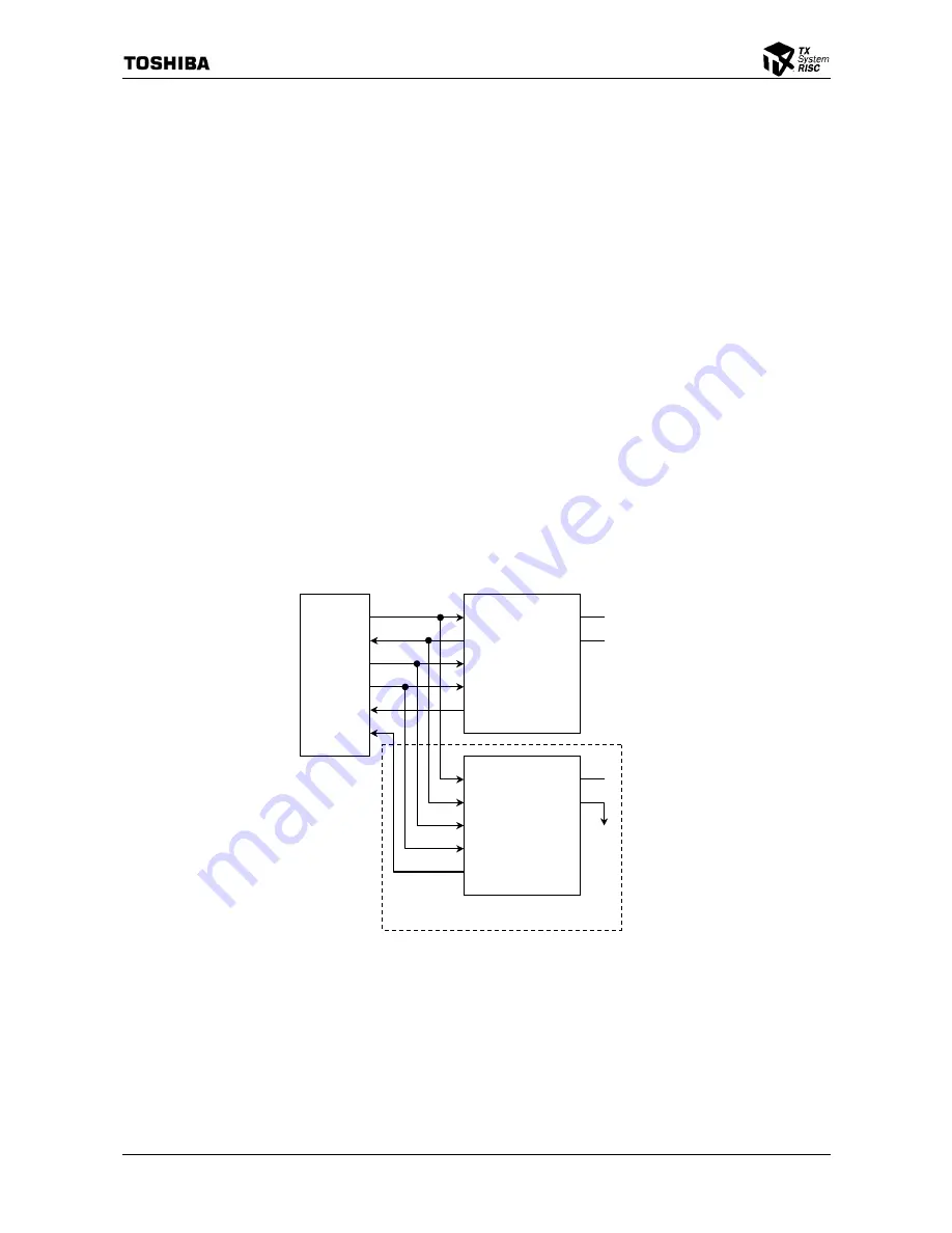
The ACLC module has two SDIN (named as SDATA_IN in the AC’97 specification) signals and
supports up to two CODECs to be connected. This section shows some system configuration diagrams
for typical usages. Note that the diagrams shown here is intended to provide conceptual understanding
and some components may be necessary on the actual circuit board to ensure proper electrical signals.
The diagrams assume CODECs compliant with the CODEC ID strapping recommendation described in
the section D.5.2 of the AC’97 revision 2.1 specification.
14.3.1.1 Stereo Audio and Optional Modem Connection
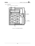
Figure 14.3.1 Stereo Audio and Optional Modem Connection Diagram
SDIN1
ACRESET
*
BITCLK
SYNC
SDOUT
SDIN0
ACLC
CID0
RESET#
BIT_CLK
SYNC
SDATA_OUT
SDATA_IN
Audio CODEC (CODEC ID=‘00’)
CID1
CID0
RESET#
BIT_CLK
SYNC
SDATA_OUT
SDATA_IN
Optional Modem CODEC (CODEC ID=’01’)
CID1
GND
Содержание TMPR4925
Страница 1: ...64 Bit TX System RISC TX49 Family TMPR4925 Rev 3 0 ...
Страница 4: ......
Страница 15: ...Handling Precautions ...
Страница 16: ......
Страница 18: ...1 Using Toshiba Semiconductors Safely 1 2 ...
Страница 40: ...3 General Safety Precautions and Usage Considerations 3 18 ...
Страница 42: ...4 Precautions and Usage Considerations 4 2 ...
Страница 43: ...TMPR4925 ...
Страница 44: ......
Страница 54: ...Chapter 1 Features 1 8 ...
Страница 58: ...Chapter 2 Block Diagram 2 4 ...
Страница 88: ...Chapter 4 Address Mapping 4 12 ...
Страница 226: ...Chapter 8 DMA Controller 8 58 ...
Страница 260: ...Chapter 9 SDRAM Controller 9 34 ...
Страница 480: ...Chapter 15 Interrupt Controller 15 32 ...
Страница 554: ...Chapter 19 Real Time Clock RTC 19 8 ...
Страница 555: ...Chapter 20 Removed 20 1 20 Removed ...
Страница 556: ...Chapter 20 Removed 20 2 ...
Страница 564: ...Chapter 21 Extended EJTAG Interface 21 8 ...
Страница 580: ...Chapter 22 Electrical Characteristics 22 16 ...
Страница 586: ...Chapter 23 Pin Layout Package 23 6 23 2 Package Package Type Package Code 256 pin PBGA PBGA 4L P BGA256 2727 1 27A4 ...
Страница 588: ...Chapter 24 Usage Notes 24 2 ...
Страница 590: ...Appendix A TX49 H2 Core Supplement A 2 ...


