Chapter 7 External Bus Controller
7-25
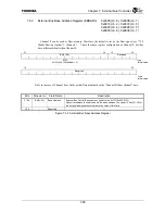
7.4.1
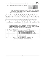
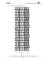
External Bus Channel Control Register (EBCCRn) 0x9000 (ch. 0), 0x9008 (ch. 1)
0x9010 (ch. 2), 0x9018 (ch. 3)
0x9020 (ch. 4), 0x9028 (ch. 5)
0x9030 (ch. 6), 0x9038 (ch. 7)
Channel 0 and 7 can be used as Boot memory. Therefore, the default is set by the Boot signal (see
“7.3.2 Global/Boot-up Options”). Channels 1 - 7 have the same register configuration as Channel 0, but
they have different defaults than Channel 0.
31 30 29 27 26 25 24 23 22 21 20 19 18 17 16
LDEA EACK
Reserved PCM
PCS
Reserved
BSZ PM PWT
R/W
R/W
R/W
R/W R/W
R/W
R/W R/W R/W
: Type
~A[5](ch0,7)/
0(ch1~6)
~A[5]/0
000 000(ch0-6)/001(ch7) 0
1(ch0,7)/
0(ch1~6)
A[13:12](ch0,7)/
00(ch1~6)
0 0
11(ch0,7)/00(ch1-6)
: Initial value
15 12
11 8 7 6 5 4 3 2
0
WT CS
BC
RDY
SP
ME
SHWT
R/W
R/W
R/W
R/W R/W R/W
R/W
: Type
1111(ch0,7)/0000(ch1~6) 0010(ch0,7)/0000(ch1-6)
A[11]
(ch0,7)/
0(ch1-6)
0(ch0-6)/
1(ch7)
A[4:3]/00 A[8]/0
000(ch0-6)/111(ch7)
: Initial value
Only in the case of Channel 0 is fields with different defaults in the “Channel 0/Other channel” state.
D[ ] represents the corresponding Data[ ] signal value when the RESET* signal is deasserted. A[ ] represents
the corresponding ADDR[ ] signal value when the RESET* signal is deasserted.
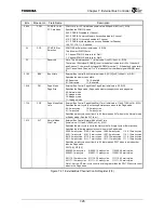
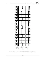
Bits Mnemonic Field
Name
Description
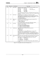
31 LDEA
Latch Data at
External ACK
*
Latch Data at External ACK
*
(Initial value: ~A[5](ch0,7)/0(ch1~6), R/W)
Specifies the data latched timing in the external ACK
*
input mode.
0 : Data is latched for External ACK
*
Input mode Reads at OE
*
active.
1 : Data is latched for External ACK
*
Input mode Reads at ACK
*
active.
30 EACK
ACK
*
Input
Active
ACK
*
Input Active (Initial value: ~A[5]/0, R/W)
Enable ACK
*
Input mode.
0 : ACK
*
Input mode is disabled.
1 : ACK
*
Input mode is enabled.
29 : 27
⎯
Reserved
Note: These bits are always set to “0” (Initial value: 000, R/W).
Figure 7.4.1 External Bus Channel Control Register (1/3)
Содержание TMPR4925
Страница 1: ...64 Bit TX System RISC TX49 Family TMPR4925 Rev 3 0 ...
Страница 4: ......
Страница 15: ...Handling Precautions ...
Страница 16: ......
Страница 18: ...1 Using Toshiba Semiconductors Safely 1 2 ...
Страница 40: ...3 General Safety Precautions and Usage Considerations 3 18 ...
Страница 42: ...4 Precautions and Usage Considerations 4 2 ...
Страница 43: ...TMPR4925 ...
Страница 44: ......
Страница 54: ...Chapter 1 Features 1 8 ...
Страница 58: ...Chapter 2 Block Diagram 2 4 ...
Страница 88: ...Chapter 4 Address Mapping 4 12 ...
Страница 226: ...Chapter 8 DMA Controller 8 58 ...
Страница 260: ...Chapter 9 SDRAM Controller 9 34 ...
Страница 480: ...Chapter 15 Interrupt Controller 15 32 ...
Страница 554: ...Chapter 19 Real Time Clock RTC 19 8 ...
Страница 555: ...Chapter 20 Removed 20 1 20 Removed ...
Страница 556: ...Chapter 20 Removed 20 2 ...
Страница 564: ...Chapter 21 Extended EJTAG Interface 21 8 ...
Страница 580: ...Chapter 22 Electrical Characteristics 22 16 ...
Страница 586: ...Chapter 23 Pin Layout Package 23 6 23 2 Package Package Type Package Code 256 pin PBGA PBGA 4L P BGA256 2727 1 27A4 ...
Страница 588: ...Chapter 24 Usage Notes 24 2 ...
Страница 590: ...Appendix A TX49 H2 Core Supplement A 2 ...

